Pulse wave analyzer and blood pressure estimator using the same

a pulse wave analyzer and estimator technology, applied in the field of pulse wave analyzers, can solve the problems of easy disturbance of waveforms, easy to give pressure to examinees, and inability to detect peak positions with high accuracy, etc., to achieve the effect of high accuracy, large noise influence, and high accuracy

Active Publication Date: 2012-03-29
DENSO CORP
View PDF1 Cites 48 Cited by
  • Summary
  • Abstract
  • Description
  • Claims
  • Application Information

AI Technical Summary

Benefits of technology

[0011]In the pulse wave analyzer configured as set forth above, base points for segmenting the pulse wave signal are determined using feature points of ECG signals. Then, based on the base points, pulse wave signal pieces are cut off from the pulse wave signals. Comparing with pulse wave signals, ECG signals have definite feature points (e.g., peaks of waveforms). Accordingly, the feature points can be identified with high accuracy without performing differentiation. Thus, large noise influence is unlikely to be caused, which would have been caused if differentiation has been performed. In this way, pulse wave signal pieces are cut off on a beat-by-beat basis with high accuracy, leading to appropriate averaging of pulse waves and calculation of a reference pulse wave with high accuracy.
[0012]The “coefficient” here enables weighting of each of the pulse wave signal pieces when these signals are averaged. The coefficient may be set such that a separate pulse wave signal having higher reliability is more heavily weighted. Alternatively, the coefficient may be set to the same value (e.g., “1”) for all the pulse wave signal pieces without performing weighting.
[0013]The “accuracy of cut-off” here refers to the degree of correctness in the uniformity (identicalness) of the waveforms of the cut-off pulse wave signal pieces. When the accuracy of cut-off is low, the peaks of the pulse waveforms (in particular, waveforms after differentiation) will be broadened (waveforms will be obtuse). Therefore, for example, feature points used for blood pressure estimation may no longer be detected. Also, the “accuracy of a reference pulse wave” refers to the degree of broadening in the peak of the waveform. Thus, higher accuracy of a reference pulse wave means that the peak is less broadened

Problems solved by technology

However, use of a cuff raises a problem of giving feeling of pressure to the examinee due to the inflation of the cuff or a problem of disabling continuous measurement of blood pressure.
However, such a differentiation raises a problem of allowing the waveforms to be easily affected by disturbance.
However, when large disturbance is caused, these peak positions cannot be detected with high accuracy.
As a result, the accuracy in cut-off intervals of the pulse wave signals is lowered, and thus the effect of averaging is not well exerted, or the addition carried out in the averaging is likely to cause further disturbance in the waveforms of the pulse wave signals.
Thus, large noise influence is unlikely to be caused, which would have been caused if differentiation has been performed.
Therefore, for example, feature points used for blood pressure estimation may no longer be detected.
R-peaks, each having a large height and a sharp peak, are easily detected and unlikely to cause errors.

Method used


Image

  • Pulse wave analyzer and blood pressure estimator using the same
  • Pulse wave analyzer and blood pressure estimator using the same
  • Pulse wave analyzer and blood pressure estimator using the same

Examples


first embodiment

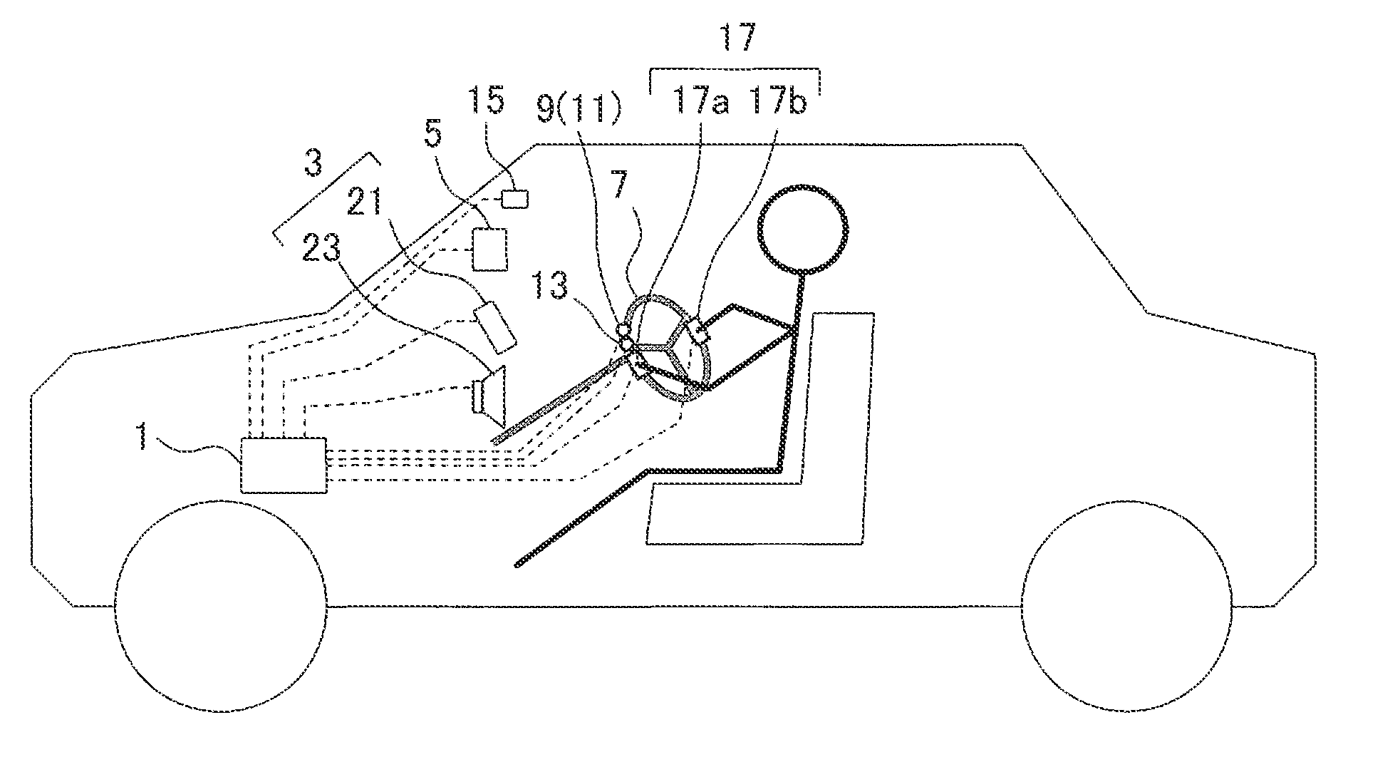
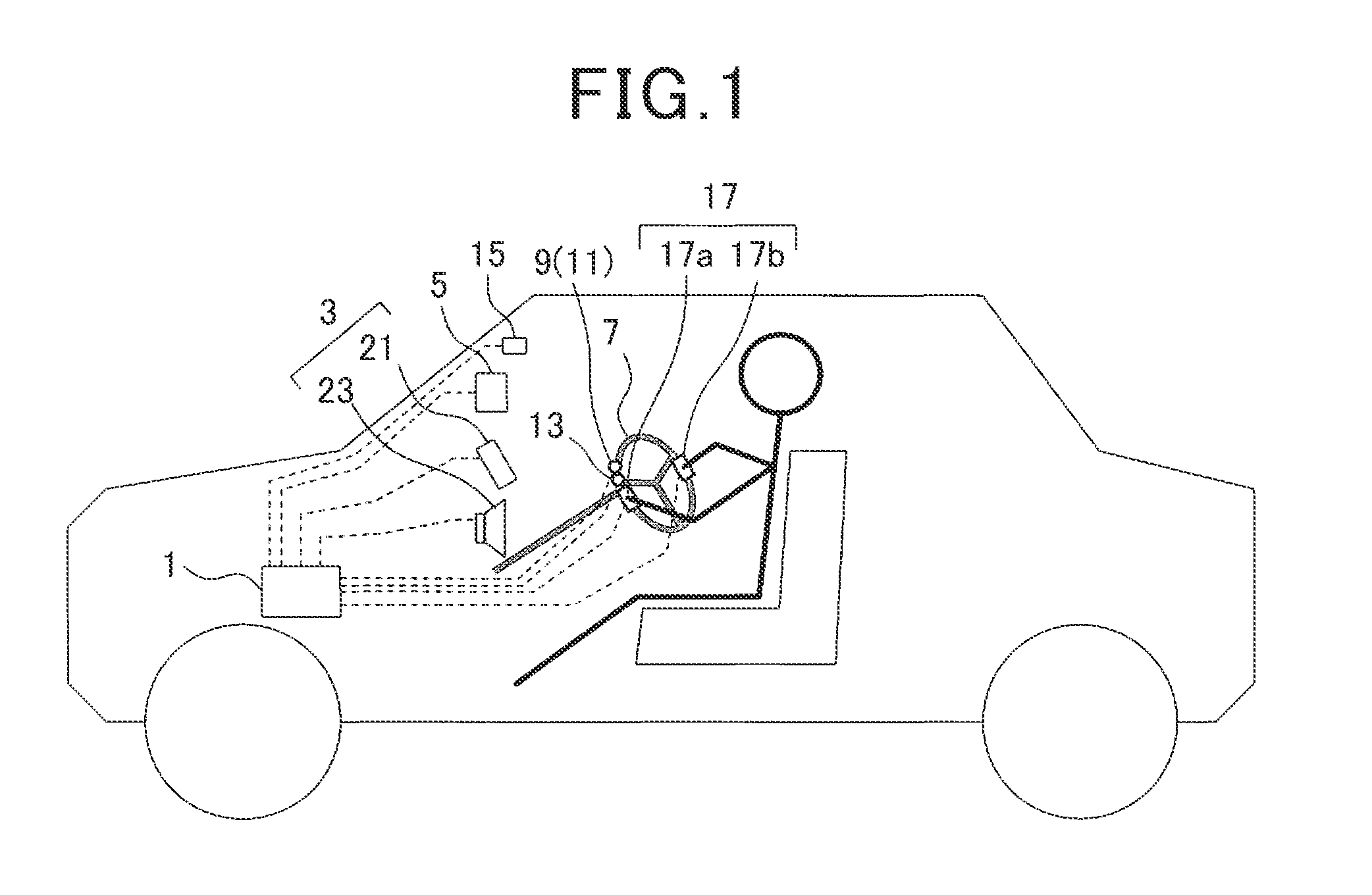
[0057]Referring to FIGS. 1 to 7, a first embodiment of the present invention is described. The first embodiment exemplifies a blood pressure estimation system which is installed in a vehicle (automobile) to measure blood pressure of the driver.

[0058]FIG. 1 is an explanatory view illustrating a general configuration of the blood pressure estimation system according to the first embodiment. This blood pressure estimation system functionally includes a pulse wave analyzer according to the present invention.

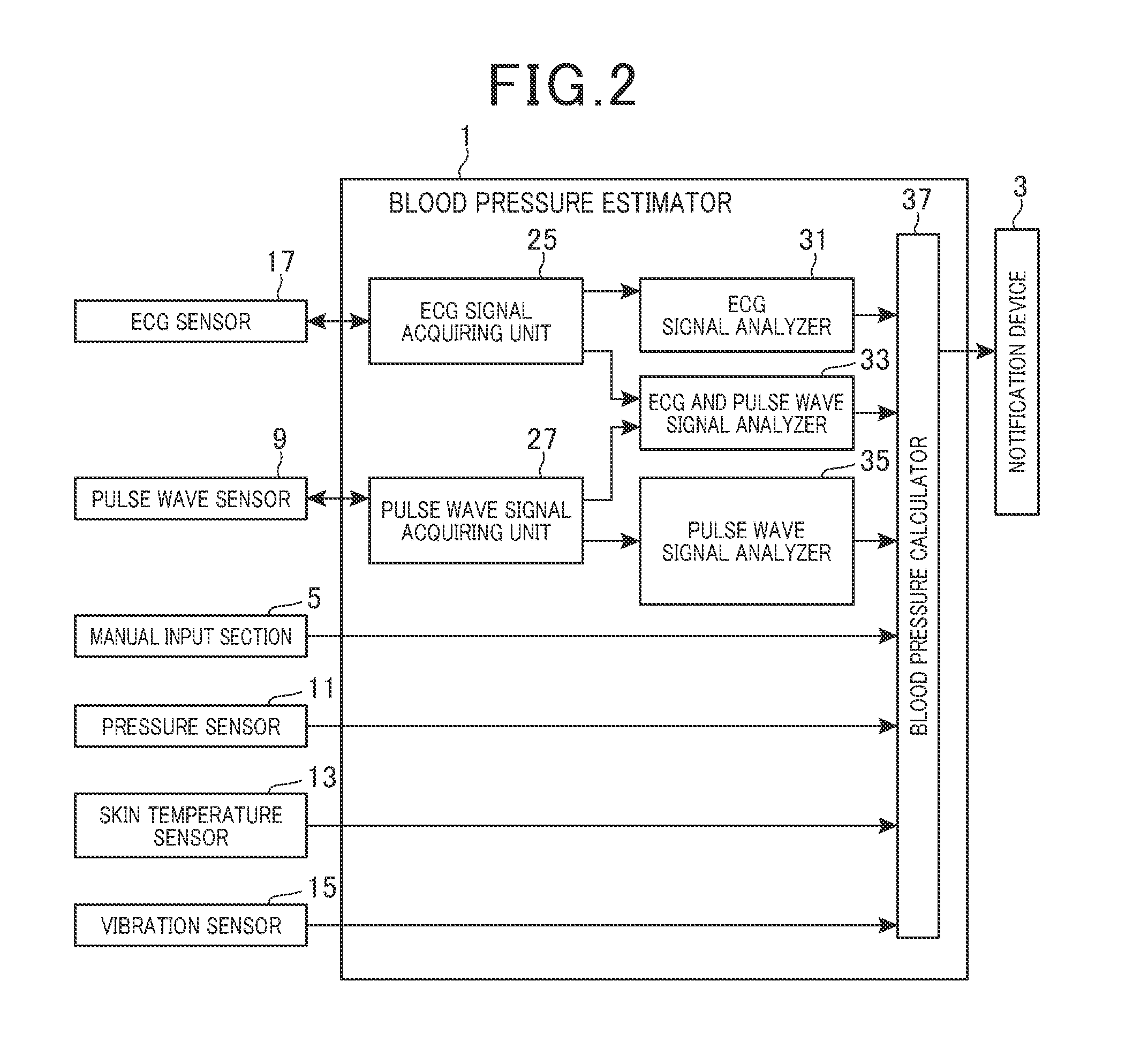
[0059]As shown in FIG. 1, the blood pressure estimation system includes a control unit 1, notification device 3, manual input device 5, pulse wave sensor 9, pressure sensor 11, skin temperature sensor 13, vibration sensor 15 and ECG (electrocardiographic) sensor 17. The notification device 3 notifies the driver, for example, of information. The manual input device 5 enables manual input of data. The pulse wave sensor 9 is attached to a steering wheel 7. The pressure sensor 11 is atta...

second embodiment

[0100]Referring now to FIGS. 8A to 8C, 9 and 10, hereinafter is described a blood pressure estimation system according to a second embodiment of the present invention. The blood pressure estimation system of the second embodiment basically has the same configuration as that of the blood pressure estimation system of the first embodiment. However, in the second embodiment, contents of processes performed in the system are partially changed. In the following description, description is given centering on the changes from the first embodiment, omitting the description of parts similar to those of the first embodiment. Further, the components identical with or similar to those of the first embodiment are given the same reference numerals for the sake of omitting unnecessary explanation.

[0101]Hereinafter is described a process of calculating a reference pulse wave in the blood pressure system of the second embodiment. In the second embodiment, every time a new separate pulse wave signal ...


PUM


Abstract

In a pulse wave analyzer, an ECG signal and a pulse wave signal are detected from an object to be analyzed. A plurality of feature points are extracting from the acquired ECG signal, the feature points appearing in a waveform of the ECG signal. The acquired pulse wave signal is segmented into a plurality of pulse wave signal pieces based on times at which the feature points appear. Each of the pulse wave signal pieces is segmented every heart beat. A reference pulse wave is calculated based on the plurality of pulse wave signal pieces, by multiplying the pulse wave signal pieces by coefficients and averaging the pulse wave signal pieces multiplied by the coefficients. The reference pulse wave is used to estimate the blood pressure of the object.

Description

CROSS-REFERENCE TO RELATED APPLICATION[0001]This application is based on and claims the benefit of priority from earlier Japanese Patent Application No. 2010-219408 filed Sep. 29, 2010, the description of which is incorporated herein by reference.BACKGROUND[0002]1. Technical Field[0003]The present invention relates to a pulse wave analyzer that analyzes pulse wave signals and a blood pressure estimating using the pulse wave analyzer.[0004]2. Related Art[0005]It is known that a cuff is used in general in measuring a blood pressure. However, use of a cuff raises a problem of giving feeling of pressure to the examinee due to the inflation of the cuff or a problem of disabling continuous measurement of blood pressure.[0006]In this regard, recently, a different measurement technique is under development. In this measurement technique, pulse wave signals are analyzed to obtain a pulse wave velocity, feature points of pulse waves, and the like, for the calculation of a blood pressure (refe...

Claims


Application Information

Patent Timeline
Patent Type & Authority Applications(United States)
IPC IPC(8): A61B5/021A61B5/0402A61B5/352
CPCA61B5/01A61B5/02125A61B5/7239A61B5/6843A61B5/6893A61B5/0402A61B5/318
Inventor FUTATSUYAMA, KOUKIFUKUMOTO, HARUTSUGUMAKAGAWA, TSUYOSHIMITSUMOTO, NAOKIIKEGAMI, TATSUYA
Owner DENSO CORP
Why Eureka
Try Eureka