Spinal implants

a technology for surgical implants and implants, applied in the field of surgical implants, can solve the problems of pain in the back and radicular muscles, pain in the nerve roots, bone growth, etc., and achieve the effect of enhancing the performance and stability of surgical implants and improving the contact of implants

Active Publication Date: 2012-03-29
SPINEART
View PDF64 Cites 29 Cited by
  • Summary
  • Abstract
  • Description
  • Claims
  • Application Information

AI Technical Summary

Benefits of technology

[0016]Disclosed are improved surgical implant systems configured to maximize stability of the implant under various anatomical conditions. In some embodiments, the implant has a multi-axial tooth geometry that helps prevent post-operative migration of the implant and / or that helps improve the stability of the surgical implant. Additionally or alternatively, the implant has surface contours that help eliminate points of contact between the implant and the endplate and thus help improve stability of the implant.
[0018]The above features, which may be used in conjunction with one another or separately, help align the implant more closely to the intervertebral space and / or resist motion along both axes of the endplate planes by improved contact of the implant with the endplate surfaces. Such improved contact enhances the performance and stability of these surgical implants.

Problems solved by technology

Degenerative disc disease is typically caused by a loss of disc space height, leading to a narrowing of the neural foramen and subsequent neural compression, and causing back and radicular pain.
This movement of the vertebral body narrows the foramen and results in painful pressure on the nerve roots.
Once the implant containing the graft material is properly placed in the disc space, a biological reaction is triggered, which results in bone growth.
These point contacts may result in substantial discomfort and pain for the patient and contribute very little to the prevention of post-operative migration of the implant.
In fact, the non-optimal contact between the implant and the vertebral walls increases the likelihood of post-operative movement of the implant, decreases the chance for fusion, and increases Pseudoarthrodesis.
The interbody space for lumbar surgery has always challenged surgeons trying to access the space to achieve arthrodesis.
All of these techniques have limitations as well as complications, as they involve extensive nerve root retraction as well as destabilization through destruction of bony and ligamentous structures.
Although longer, straight implants have been placed across the disc space with some success, the lordotic angle of the spine is harder to properly match with these straight implants.
Despite the benefits of the TLIF procedure, TLIF still suffers from limitations involving bony and soft tissue destruction and bilateral pathology.
However, the anterior approach (from the patient's abdomen) to the disc space also presents challenges and limitations because of the potential of vascular injuries.
It is known in the art that revision surgery is greatly complicated by scarring from the initial procedure.
Another drawback of existing systems and techniques for XLIF procedures is that implants are usually undersized from a medial-lateral and anterior-posterior approach.
In existing systems, regardless of the surgical approach, the implants are not designed to fit the anatomical contours of the spinal cavity.
Thus, the implants are subject to post-operative migration and repulsions, resulting in significant pain and discomfort for the patient.

Method used


Image

  • Spinal implants
  • Spinal implants
  • Spinal implants

Examples


Embodiment Construction

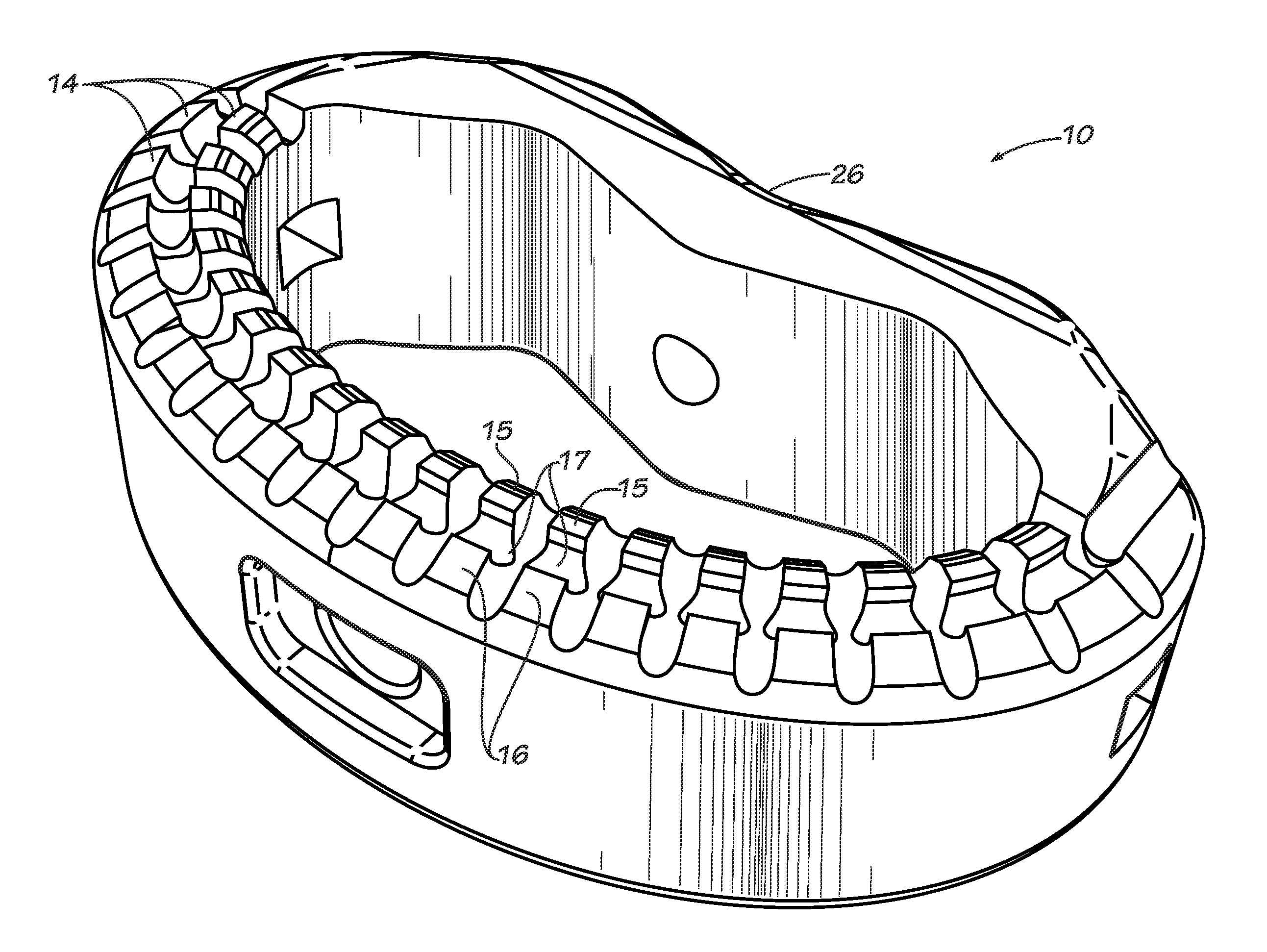
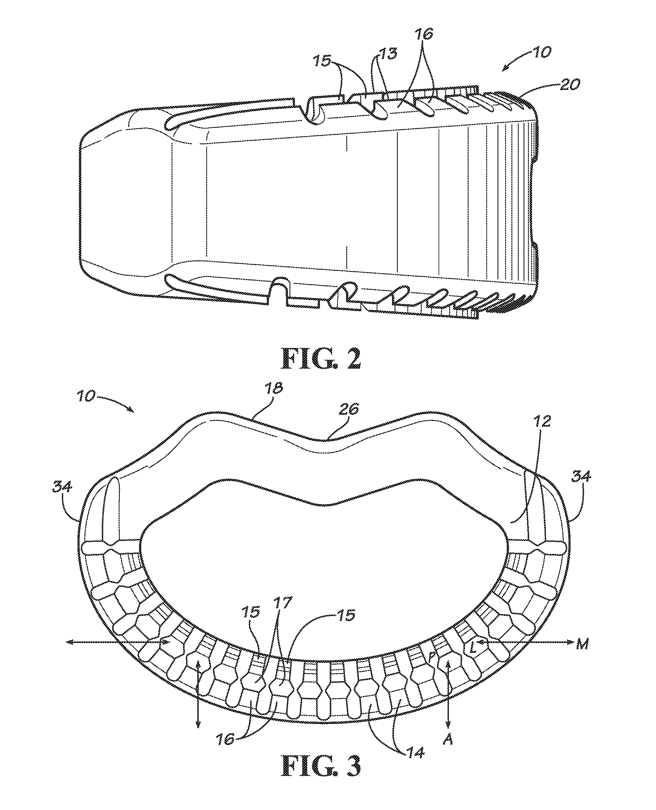
[0031]Disclosed are interbody implant systems comprising implants with unique profiles and / or other features that help prevent movement and migration of the implants once the implants have been placed in the interbody disc space. The interbody implants are useful for implants of any size or style, but are particularly useful for implants of larger size that may be used in procedures such as ALIF or XLIF. The disclosed implants may also be used in other procedures, such as TLIF and PLIF. The interbody implants may be made of titanium, carbon fiber, allograft, or other suitable material including, but not limited to, biocompatible materials such as the Paek family of polymers. Those of ordinary skill in the art will readily appreciate other materials of which the implants may be composed.

[0032]As described in detail below, features of the disclosed implants maximize stability of the implant under various anatomical conditions. In some embodiments, the implant includes surface contours...


PUM


Abstract

Disclosed are improved spinal implants that are configured to help prevent post-operative migration of the implant. In some embodiments, the implant system includes multi-axial tooth geometry and other geometrical configurations such as but not limited to peripheral curvatures that aid in the prevention of such post-operative migration. Also disclosed are asymmetrical implants having superior and inferior surfaces with different angulations relative to the sagittal midline.

Description

RELATED APPLICATIONS[0001]This application claims the benefit of U.S. Provisional Application Ser. No. 61 / 378,445 filed Aug. 31, 2010 titled “Spinal Implants with Multi-Axial Tooth Geometry,” the content of which is hereby incorporated by reference.FIELD OF THE INVENTION[0002]This invention generally relates to surgical implants for use in spinal surgery.BACKGROUND[0003]Degenerative disc disease is typically caused by a loss of disc space height, leading to a narrowing of the neural foramen and subsequent neural compression, and causing back and radicular pain. Instability of the posterior elements can lead to conditions such as spondylolisthesis or spinal stenosis. In the case of spondylolisthesis, a vertebral body slips forward in relation to an adjacent vertebrae. This movement of the vertebral body narrows the foramen and results in painful pressure on the nerve roots. In the case of spinal stenosis, the spinal canal narrows and compresses the spinal cord and nerves.[0004]Degene...

Claims


Application Information

Patent Timeline
Patent Type & Authority Applications(United States)
IPC IPC(8): A61F2/44
CPCA61F2/442A61F2/4465A61F2/447A61F2002/2835A61F2002/3023A61F2002/4475A61F2002/30822A61F2002/30828A61F2002/3083A61F2002/30904A61F2002/30266A61F2220/0016A61F2002/30593
Inventor JAMES, STEPHEN B.SCLAFANI, ADAMFLICKINGER, ERIC
Owner SPINEART
Why Eureka
Try Eureka