Vehicle drive device

a technology of drive device and friction member, which is applied in the direction of engine-driven generator propulsion, mechanical equipment, transportation and packaging, etc., can solve the problems of increasing the weight of the oil pump itself, reducing energy efficiency, and increasing the pump, so as to reduce the amount of oil supplied to the friction member, the effect of efficient cooling

Inactive Publication Date: 2012-04-05
AISIN AW CO LTD
View PDF12 Cites 42 Cited by
  • Summary
  • Abstract
  • Description
  • Claims
  • Application Information

AI Technical Summary

Benefits of technology

[0005]In view of the foregoing, it is desirable to provide a vehicle drive device in which both friction members and a rotary electric machine can be efficiently cooled while suppressing the amount of oil supplied to the friction members to be small.

Problems solved by technology

In such a configuration, in order to secure sufficient capability to cool the friction members, it is necessary to supply a large amount of oil to the friction members, which requires a large oil pump, however.
As a result, not only energy for driving the pump is increased but also the weight of the oil pump itself is increased, which may reduce the energy efficiency.

Method used


Image

  • Vehicle drive device
  • Vehicle drive device
  • Vehicle drive device

Examples


Embodiment Construction

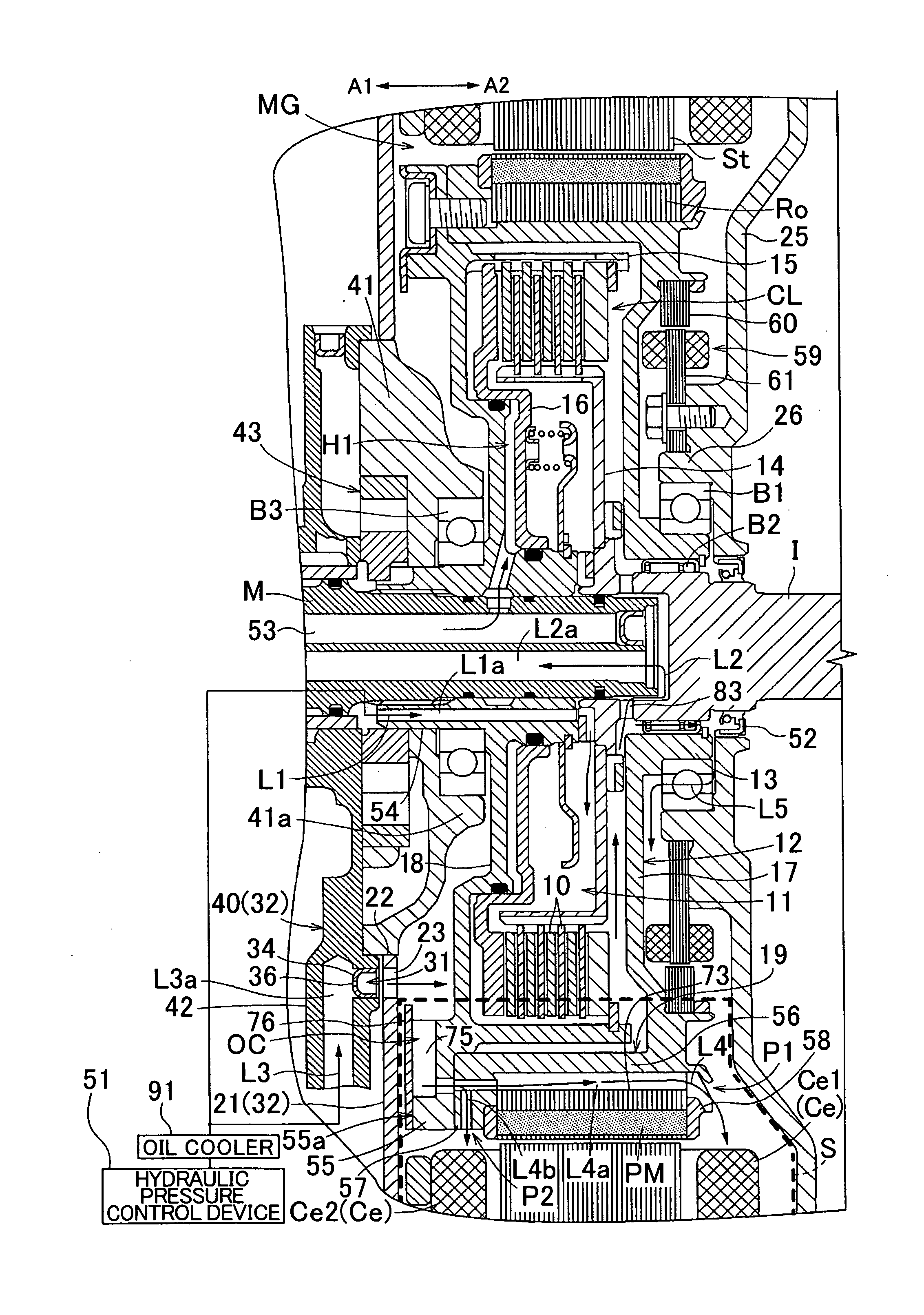
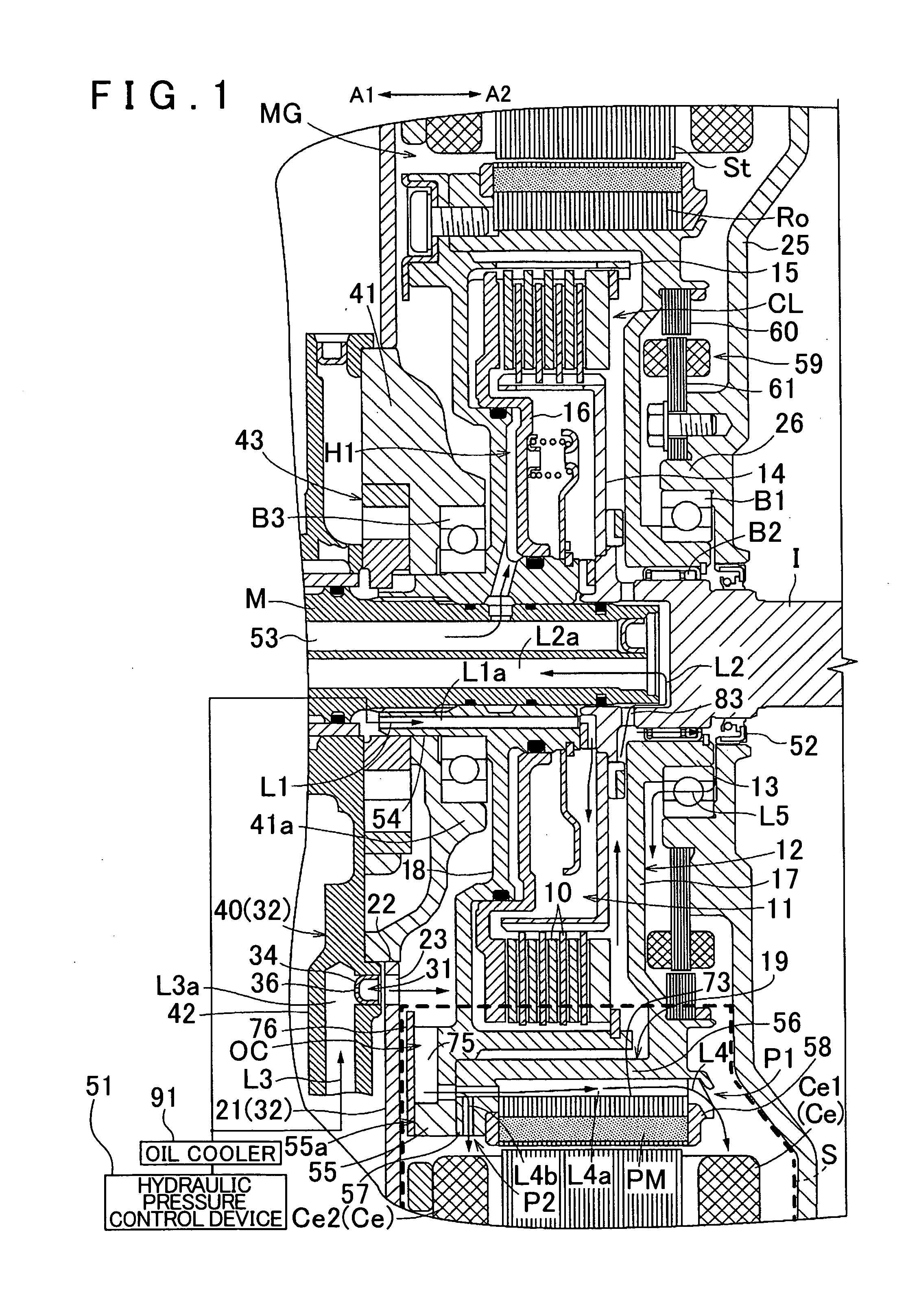
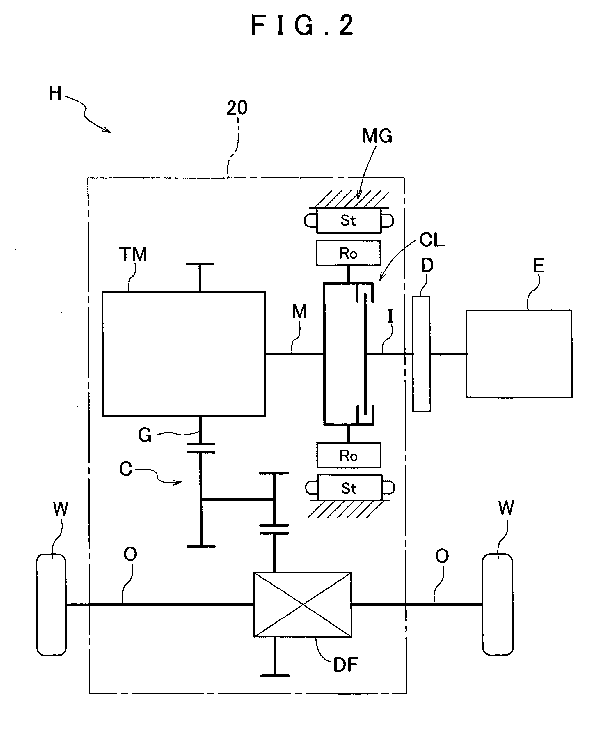
[0036]An embodiment of the present invention will be described with reference to the drawings. In the embodiment, a vehicle drive device according to the present invention is applied to a hybrid drive device. FIG. 2 is a schematic diagram showing a schematic configuration of a hybrid drive device H according to the embodiment. The hybrid drive device H is a drive device for a hybrid vehicle that uses one or both of an internal combustion engine E and a rotary electric machine MG as a drive force source for the vehicle. The hybrid drive device H is formed as a so-called one-motor parallel type hybrid drive device. The hybrid drive device H according to the embodiment will be described in detail below.

1. Overall Configuration of Hybrid Drive Device

[0037]First, the overall configuration of the hybrid drive device H according to the embodiment will be described. As shown in FIG. 2, the hybrid drive device H includes an input shaft I drivably coupled to the internal combustion engine E s...


PUM


Abstract

A vehicle drive device configured with an input member drivably coupled to an internal combustion engine. The drive device is also configured with an output member drivably coupled to wheels, a friction engagement device that selectively drivably couples the input member and the output member to each other, and a rotary electric machine provided on a power transfer path connecting between the input member and the output member. On the vehicle drive device, a housing oil chamber houses at least friction members of the friction engagement device and is filled with oil, a housing space houses the rotary electric machine, and there exists a first oil passage through which oil is supplied to the housing oil chamber. There is also a second oil passage through which oil is discharged from the housing oil chamber and a third oil passage through which oil is supplied to the housing space.

Description

[0001]The disclosure of Japanese Patent Applications No. 2010-213447 filed on Sep. 24, 2010 and No. 2011-043270 filed on Feb. 28, 2011 including the specification, drawings and abstract is incorporated herein by reference in its entirety.BACKGROUND OF THE INVENTION[0002]The present invention relates to a vehicle drive device including an input member drivably coupled to an internal combustion engine, an output member drivably coupled to wheels, a friction engagement device that selectively drivably couples the input member and the output member to each other, and a rotary electric machine provided on a power transfer path connecting between the input member and the output member.DESCRIPTION OF THE RELATED ART[0003]A device disclosed in Japanese Patent Application Publication No. JP-A-2009-72052 mentioned below is already known as an example of a vehicle drive device including an input member drivably coupled to an internal combustion engine, an output member drivably coupled to whee...

Claims


Application Information

Patent Timeline
Patent Type & Authority Applications(United States)
IPC IPC(8): B60K6/20B60L50/16
CPCB60K6/40B60K6/48B60K2006/4825B60L11/14H02K7/006H02K7/108Y02T10/70Y02T10/641Y02T10/7077F16H57/0476Y02T10/6221Y02T10/6252H02K9/19B60L50/16Y02T10/62Y02T10/64Y02T10/7072
Inventor KASUYA, SATORUKITOU, MASASHISEKI, YUICHITAKAHASHI, YUSUKESUGISAKA, SHIGERU
Owner AISIN AW CO LTD
Why Eureka
Try Eureka