Double-faced adhesive tape joining method and double-faced adhesive tape joining apparatus

a double-faced adhesive tape and joining method technology, applied in the direction of layered products, chemistry apparatus and processes, paper/cardboard articles, etc., can solve the problems of non-uniform winding of the tape, tape deformation into a cone shape, and the accuracy of the joining of the piece of double-faced adhesive tape to the substrate is reduced

Inactive Publication Date: 2012-04-12
NITTO DENKO CORP
View PDF1 Cites 9 Cited by
  • Summary
  • Abstract
  • Description
  • Claims
  • Application Information

AI Technical Summary

Benefits of technology

[0011]This invention has been made regarded to the state of the art noted above, and its primary object is to provide a method and apparatus for efficiently joining to a substrate a double-faced adhesive tape pre-cut into a shape of the substrate.
[0013]According to this method, the original master tape having a uniform thickness is rolled. Consequently, a pressure due to rolling up may be applied uniformly to a surface of the tape. Thus, when the original master tape is rolled up insufficiently as in the case of the original master tape provided with pre-cut pieces of the double-faced adhesive tape on the carrier tape, reduction in accuracy of joining the tape and serpentine following turbulent winding in transporting the tape may be suppressed as compared to the conventional method.
[0016]Moreover, the double-faced adhesive tape is fed out from the original master roll, and cut into the substrate shape to be guided to the knife edge. Accordingly, the cut double-faced adhesive tape having the separator laminated thereto may travel to the knife edge without largely bending of the original master tape. In other words, the double-faced adhesive tape may be guided to the knife edge under a proper joining condition with no inadvertent separation and floating of the separator from the piece of the double-faced adhesive tape. As a result, the piece of the double-faced adhesive tape with the separator may be separated with the knife edge and joined to the substrate while being properly pressed with a joining roller.
[0018]When the Thomson blade is adopted for substrates in various shapes, the piece of the double-faced adhesive tape having a corresponding shape thereto may be half-cut accurately within an extremely short period of time. Moreover, two or more types of Thomson blades each corresponding to the substrate shape are prepared in advance, and a cutting blade is replaced in accordance with a substrate to be processed. Accordingly, the piece of the double-faced adhesive tape corresponding to various substrates may be formed through cutting.

Problems solved by technology

As a result, non-uniform winding of the tape may occur during a transportation process when the tape is not sufficiently wound up.
Moreover, when the tape is not sufficiently wound up, the tape deforms into a cone shape when set in the apparatus.
Consequently, there arises a problem as under.
That is, the substrate and the piece of the double-faced adhesive tape deviate from each other in its joining position, which leads to joining of the piece of the double-faced adhesive tape to the substrate with lower accuracy.
Moreover, another problem may arise as under.
Thus, the foregoing problem will notably occur in rolling up the original master tape.

Method used


Image

  • Double-faced adhesive tape joining method and double-faced adhesive tape joining apparatus
  • Double-faced adhesive tape joining method and double-faced adhesive tape joining apparatus
  • Double-faced adhesive tape joining method and double-faced adhesive tape joining apparatus

Examples


Embodiment Construction

[0035]One embodiment of this invention is now to be described below with reference to the drawings.

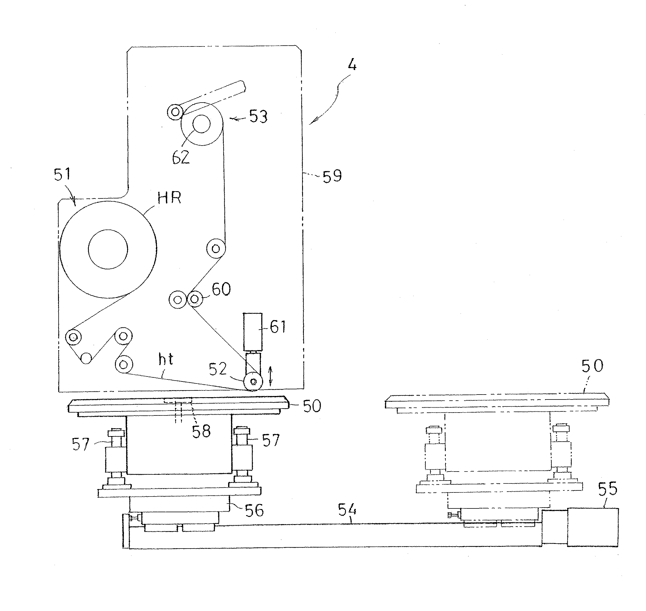
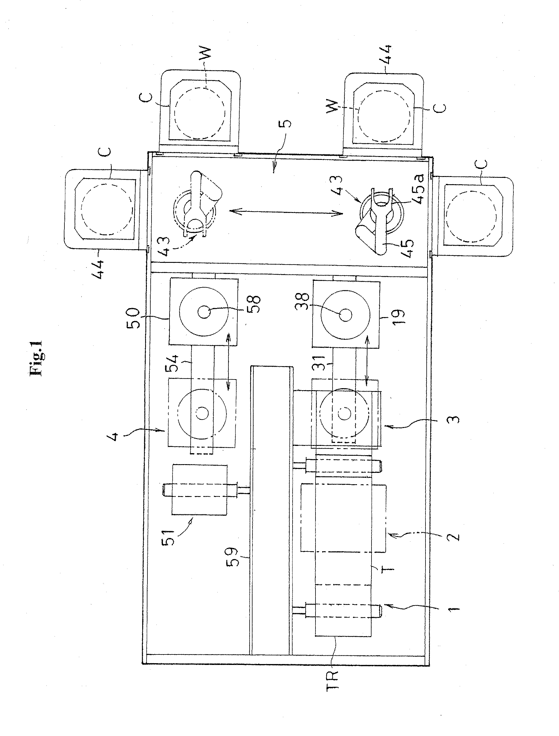
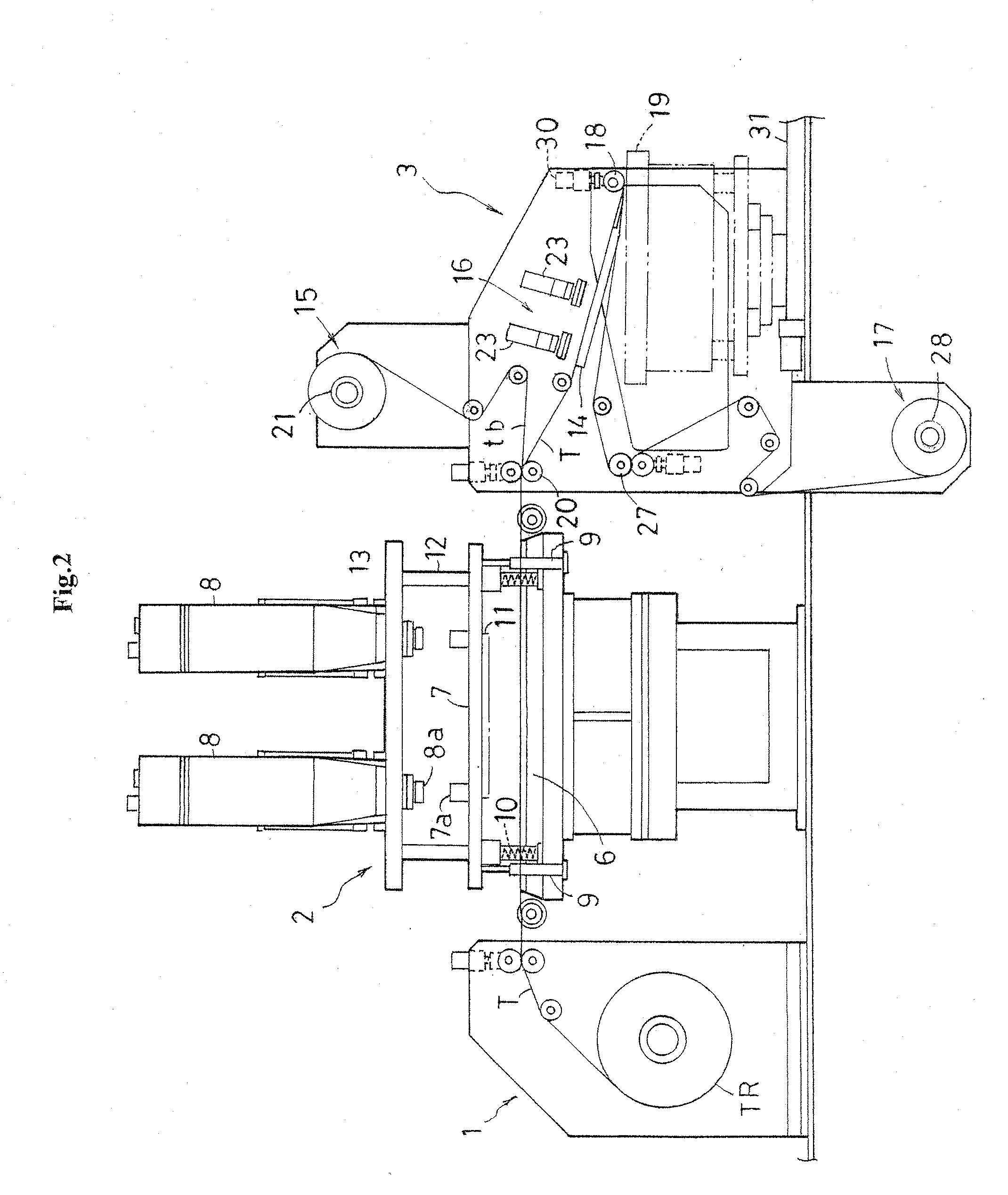
[0036]FIG. 1 is a schematic plan view of double-faced adhesive tape joining apparatus according to this invention. FIG. 2 is a side view of main components thereof.

[0037]The double-faced adhesive tape joining apparatus joins a double-faced adhesive tape for joining a support substrate for reinforcement to a surface of a semiconductor wafer W (hereinafter, simply referred to as a “wafer W”), which is one example of a substrate. A tape supply unit 1, a tape pre-cut mechanism 2, and a tape joining section 3 are placed in series in the longitudinal direction (in the left-right direction in FIG. 1) of the apparatus. A tape separating section 4 is placed on the lateral side (the upper side in FIG. 1) of the tape joining section 3. A long substrate transportation section 5 is placed in the left-right direction (a vertical direction in FIG. 1) as to face toward the tape joining section 3 and t...


PUM

PropertyMeasurementUnit
shapeaaaaaaaaaa
speedaaaaaaaaaa
rigidityaaaaaaaaaa

Abstract

An original master tape having a long carrier tape and a long double-faced adhesive tape joined thereto is guided to a knife edge to be folded back. The double-faced adhesive tape is half-cut on the carrier tape in front of the knife edge with a Thomson blade having a corresponding shape to a substrate. The original master tape is folded back at the knife edge. Accordingly, a piece of the double-faced adhesive tape cut into the substrate shape is separated from the carrier tape to be joined to the substrate traveling relatively at a speed synchronized to a separation speed.

Description

BACKGROUND OF THE INVENTION[0001](1) Field of the Invention[0002]This invention relates to a method and apparatus for joining a double-faced adhesive tape to a substrate such as a semiconductor wafer.[0003](2) Description of the Related Art[0004]In recent years, a semiconductor wafer (hereinafter, appropriately referred to as a “wafer”) tends to be thinned. Accordingly, in order to compensate for rigidity of the wafer under processing such as a back grinding process, a support substrate, such as a glass plate and a metal plate, that is formed into the same shape as the wafer is joined to a surface of the wafer via a double-faced adhesive tape.[0005]For joining the support substrate having the same shape as the wafer to the surface of the wafer via the double-faced adhesive tape, the double-faced adhesive tape is firstly joined to the surface of the wafer. Thereafter, the support substrate is joined to the wafer via the double-faced adhesive tape having the wafer joined thereto. For ...

Claims


Application Information

Patent Timeline
Patent Type & Authority Applications(United States)
IPC IPC(8): B32B38/10B32B37/14
CPCC09J5/00C09J2203/326Y10T156/12H01L21/6835H01L2221/68327H01L21/67132
Inventor YAMAMOTO, MASAYUKI
Owner NITTO DENKO CORP
Why Eureka
Try Eureka