Fluid Treatment Apparatus

a treatment apparatus and flue gas technology, applied in the direction of multi-stage water/sewage treatment, other chemical processes, separation processes, etc., can solve the problems of increasing problems, water which is used in the vehicle washing process, and water which is intended for drinking and supplied in a reticulated system often has insufficient treatment to enable safe drinking

Active Publication Date: 2012-04-12
INTPROP LTD INC +2
View PDF4 Cites 23 Cited by
  • Summary
  • Abstract
  • Description
  • Claims
  • Application Information

AI Technical Summary

Benefits of technology

[0038]Means may be provided for processing the waste from the apparatus, the processing means including a waste chamber having an inlet for receiving the waste, a vacuum or suction pump connected to the waste chamber, at least one ultraviolet light source in the chamber for destroying gas in the waste chamber and an outlet from said chamber. A fluid trap may be associated with the outlet for preventing gases passing through the outlet.

Problems solved by technology

The treating of water for the purposes of purifying the liquid particularly water or removing contaminants from water has become an increasing problem for growing communities where increasing volumes of effluent or contaminated water is generated.
Other water intended for drinking and which is supplied in a reticulated system often has insufficient treatment to enable it to be safely drunk.
Automated and non-automated vehicle washing apparatus use considerable quantities of water in washing vehicles.
Water which is used in the vehicle washing process can be contaminated with soap and detergent suds used in the washing process as well as grease, oil, brake pad dust, road grime and other contaminants.
Furthermore, a considerable volume of water is used in the washing process which is obviously undesirable from the point of view of water conservation.
Difficulties however are encountered in reusing water from vehicle washing apparatus because of the contaminants in the water used in the washing process.
Similar difficulties to that described above have been encountered where purifying or removing of contaminants from other liquids is required and additionally in purifying or removing contaminants from gases.

Method used


Image

  • Fluid Treatment Apparatus
  • Fluid Treatment Apparatus
  • Fluid Treatment Apparatus

Examples


Embodiment Construction

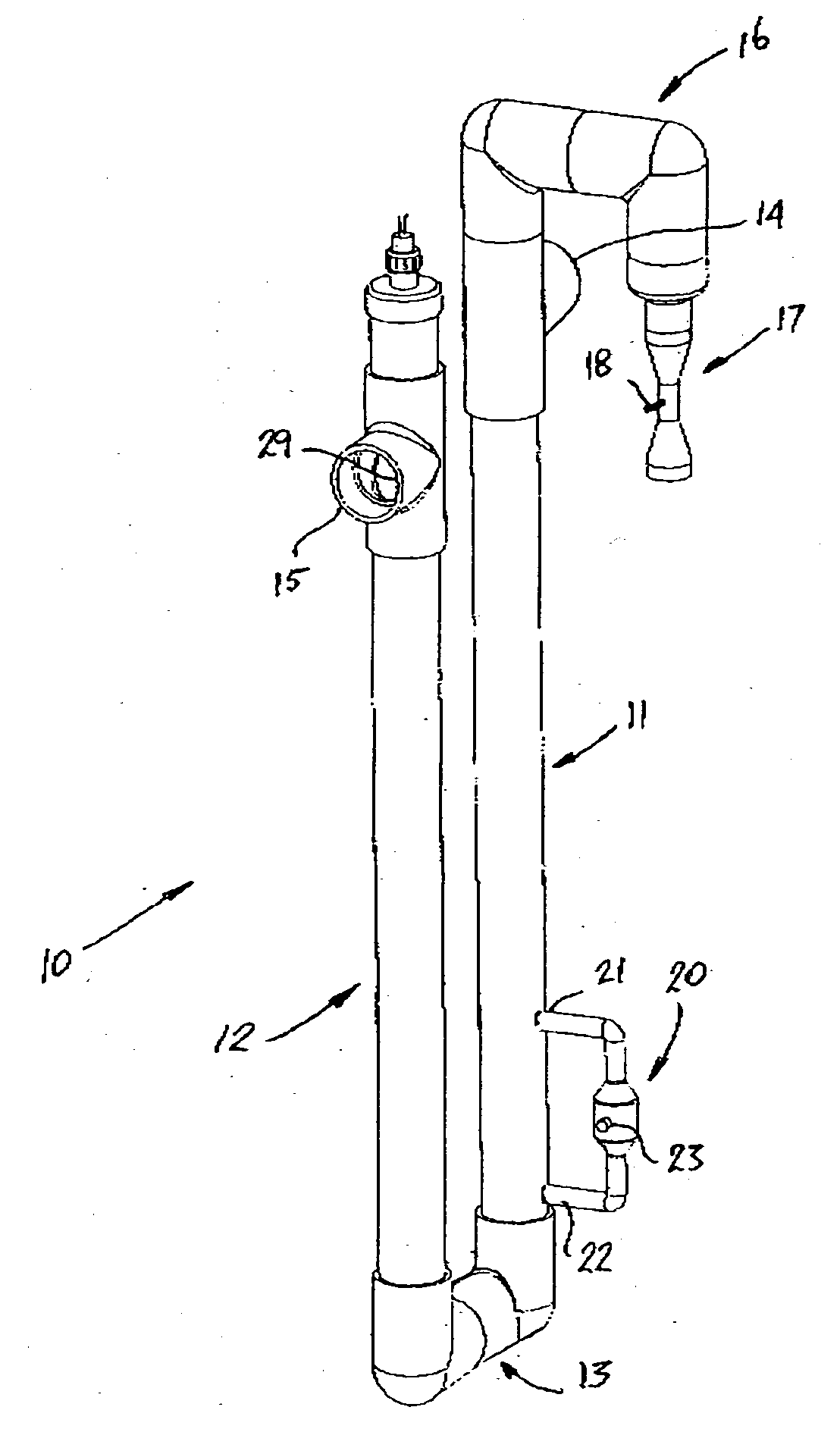
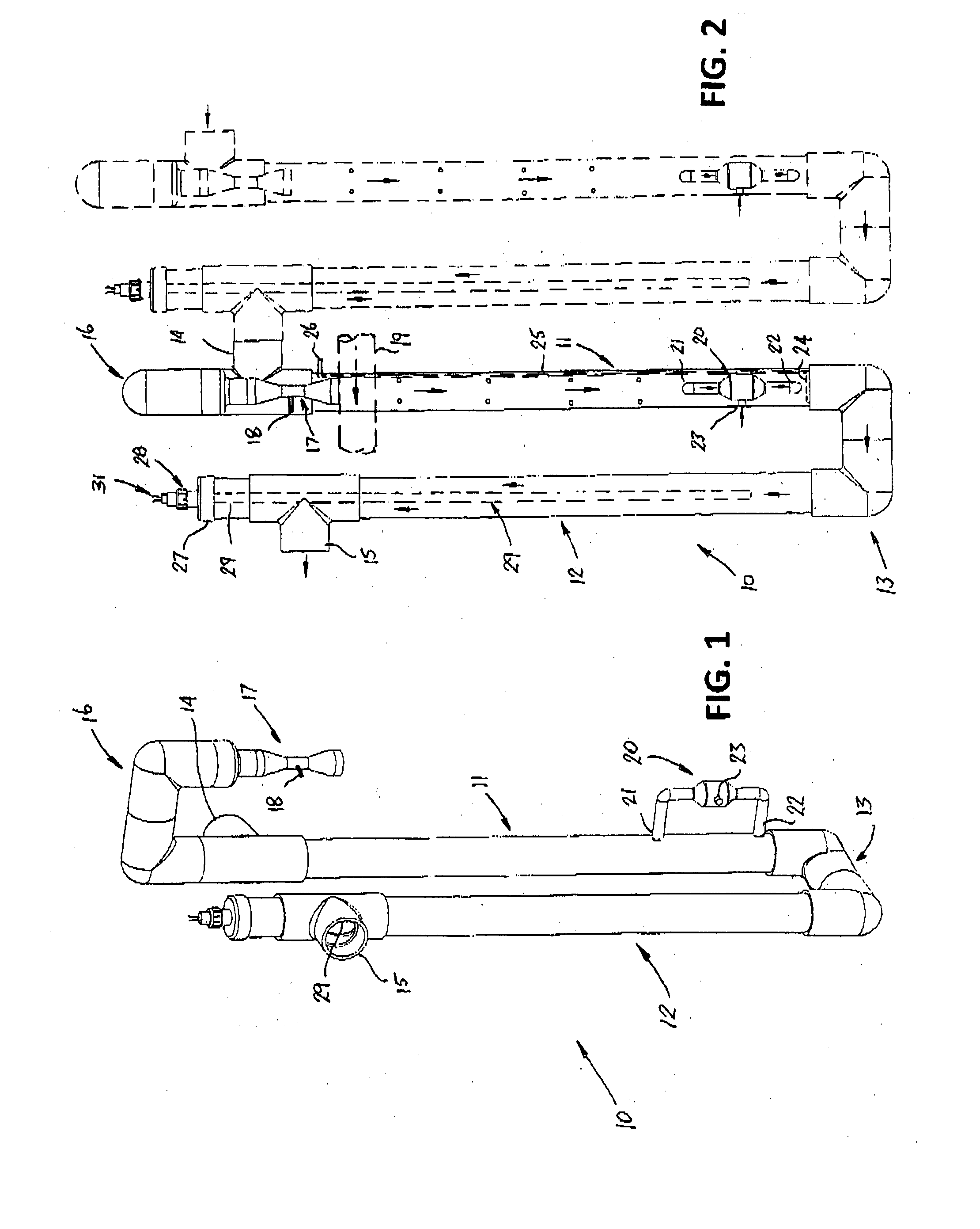
[0104]Referring to the drawings and firstly to FIGS. 1 and 2, there is illustrated a fluid treatment unit 10 which embodies the principles of the invention and which is used typically in apparatus for treating contaminated liquid which for example may be grey water, or water from a vehicle washing establishment or for treating any other fluid. The unit 10 includes a first upright elongated hollow member 11 and a second elongated member 12 which typically comprise pipes or tubes which are substantially parallel to each other and have their lower ends at substantially the same horizontal level and which in this case are fluidly joined to each other through a pair of elbow fittings which serve as a fluid transfer passage 13.

[0105]The first treatment member 11 of the unit 10 has an inlet 14 for liquid to be treated towards its upper end whilst the second or trailing member 12 includes an outlet 15 for treated liquid which is towards the upper end of the member 12 but below the inlet 14....


PUM

PropertyMeasurementUnit
angleaaaaaaaaaa
wavelengthaaaaaaaaaa

Abstract

Fluid purification or treatment apparatus (10) for treating or purifying contaminated liquids such as water which includes at least one upright elongated primary treatment chamber (11) having an inlet (14) for fluid to be treated at an upper end of the chamber (11) such that fluid flows downwardly through the chamber (11) and means (20 or 24) for introducing a sterilizing agent such as ozone or ozone enriched air into a lower end of the chamber (11) for bubbling upwardly through liquid flowing downwardly through the chamber (11), means (16) at the upper end of the chamber (11) for removing waste and an ultraviolet lamp (29) for UV treatment of the liquid, the ultraviolet lamp (29) being located in a separate chamber (12) connected to the primary treatment chamber (11) or within the primary treatment chamber (11). A plurality of chambers (11) and (12) may be provided for multiple treatment of the liquid.

Description

TECHNICAL FIELD[0001]This invention relates to fluid treatment apparatus which is suited for treating liquid such as water for the purposes of purifying, cleaning or otherwise removing impurities or contaminants in the liquid. The apparatus of the present invention is particularly suited for treatment of grey water, drinking water, swimming pool water, and water from aquaculture systems, sewerage water, and other contaminated water such as water from vehicle washing apparatus which contain soap and detergent and water containing dyes and other contaminants or colourants. The present invention may also be applied to the removal of salt from salt water to provide drinking or potable water in a desalination process or treatment of other liquids such as blood and fuels. The present invention may also be applied to the treatment of gases for the purposes of purifying gases.BACKGROUND ART[0002]The treating of water for the purposes of purifying the liquid particularly water or removing co...

Claims


Application Information

Patent Timeline
Patent Type & Authority Applications(United States)
IPC IPC(8): C02F1/32C02F1/68C02F1/78B01D43/00
CPCC02F1/32C02F9/00C02F1/78C02F1/50C02F1/722C02F1/325
Inventor CUMMINS, IAN G.
Owner INTPROP LTD INC
Why Eureka
Try Eureka