Wireless IC tag, reader-writer, and information processing system

a technology of integrated circuits and tags, applied in the field of wireless integrated circuit tags, can solve the problems of reducing the communication distance, and reducing the energy transfer efficiency between the wireless ic tag and the reader-writer, so as to increase the communication distance, and improve the energy transfer efficiency

Active Publication Date: 2012-04-12
MURATA MFG CO LTD
View PDF13 Cites 37 Cited by
  • Summary
  • Abstract
  • Description
  • Claims
  • Application Information

AI Technical Summary

Benefits of technology

[0011]In the wireless IC tag, the reader-writer, and the information processing system according to preferred embodiments of the present invention, the multiple coil-shaped antennas (coil-shaped antenna portions) transmit and receive high-frequency signals (for example, within the ultra high frequency (UHF) band or the high frequency (HF) band) at a relatively short distance. The winding axes of the multiple coil-shaped antennas (coil-shaped antenna portions) are arranged at different positions and the multiple coil-shaped antennas (coil-shaped antenna portions) have the same winding direction. Accordingly, the energy transfer efficiency is improved without an offset of currents occurring in the respective antennas (antenna portions).
[0012]According to various preferred embodiments of the present invention, it is possible to improve the energy transfer efficiency between the antenna of the reader-writer and the antennas of the wireless IC tag so as to increase the communication distance.

Problems solved by technology

However, since the two coil-shaped antennas have opposite winding directions in the wireless IC tag, the wireless IC tag has a disadvantage in that, in response to reception of a high-frequency magnetic field radiated from a loop antenna of the reader-writer, a current occurring in one coil-shaped antenna is offset by a current occurring in the other coil-shaped antenna.
Accordingly, there is a problem in that the energy transfer efficiency between the wireless IC tag and the reader-writer is reduced to decrease the communication distance.

Method used


Image

  • Wireless IC tag, reader-writer, and information processing system
  • Wireless IC tag, reader-writer, and information processing system
  • Wireless IC tag, reader-writer, and information processing system

Examples


first preferred embodiment

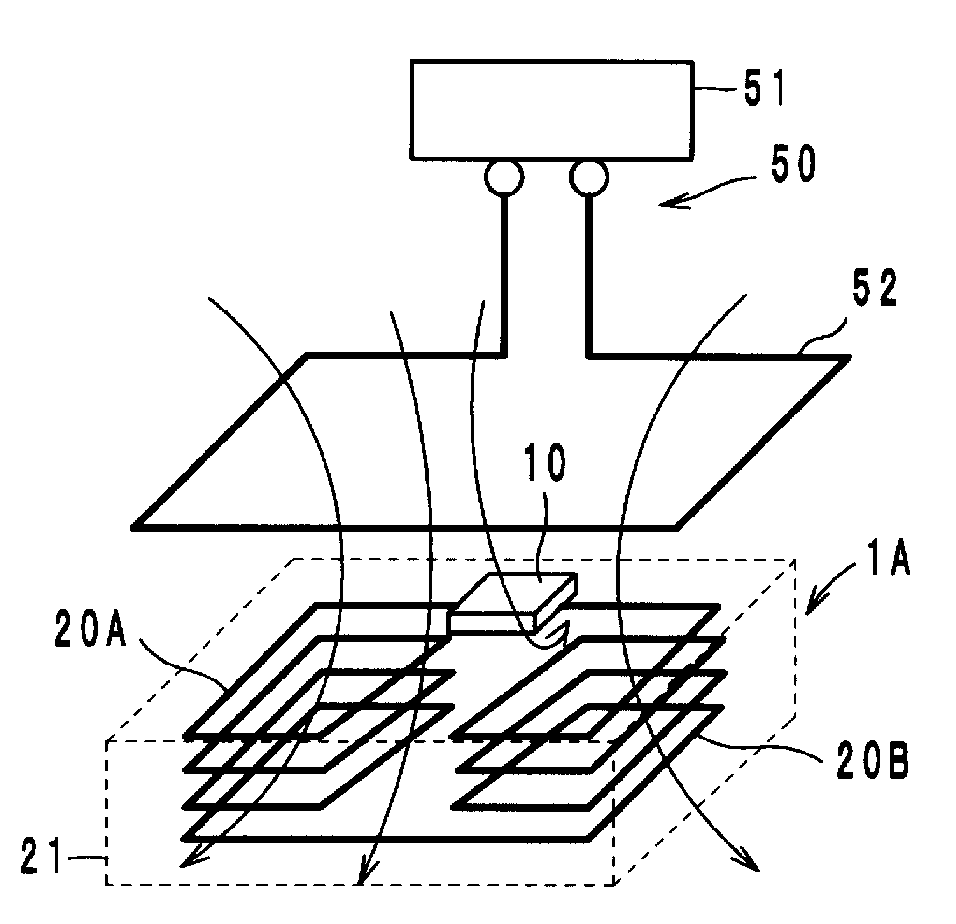
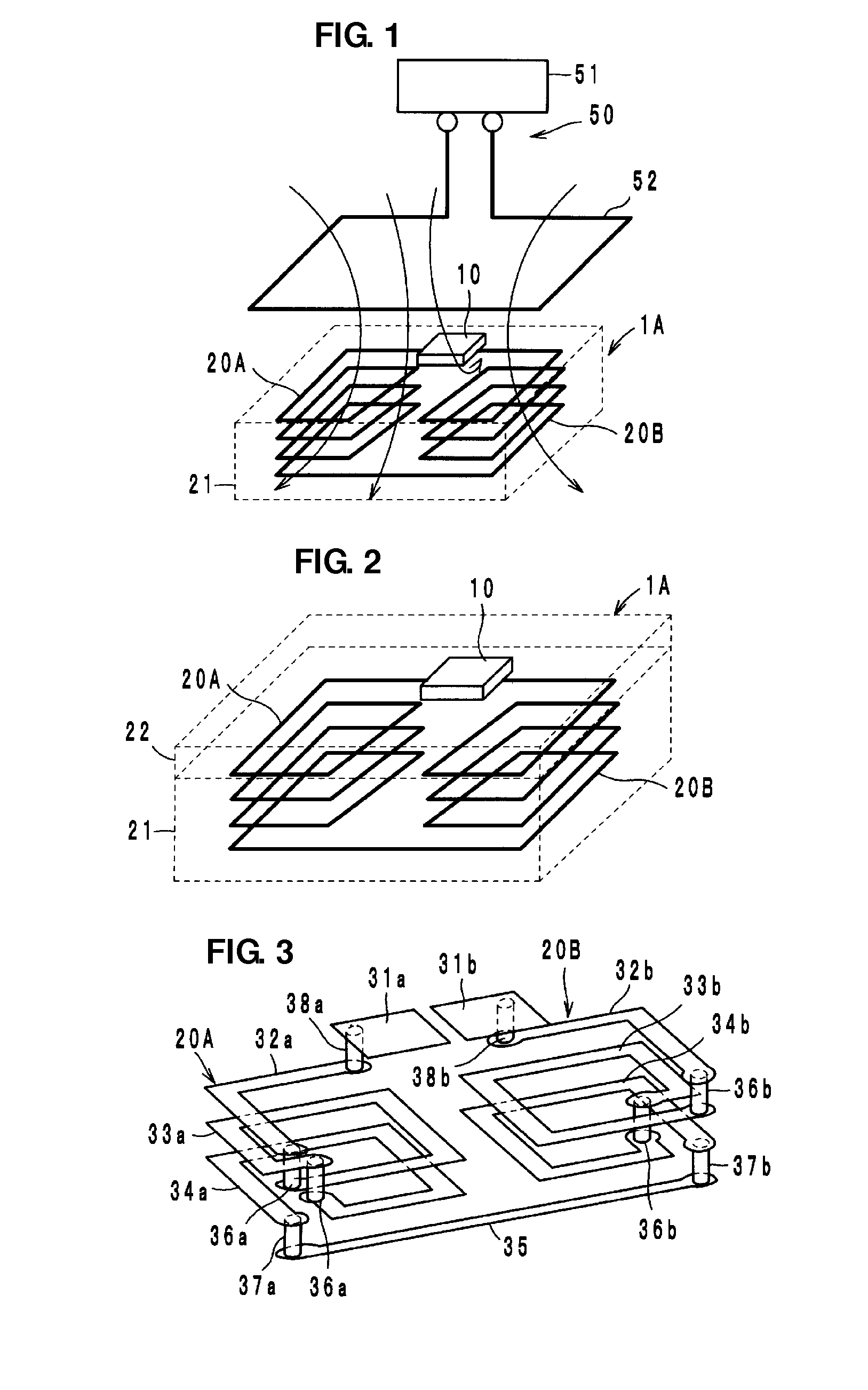
[0036]A wireless IC tag 1A according to a first preferred embodiment of the present invention preferably includes a wireless IC chip 10 that processes transmission and reception signals having certain frequencies and two coil-shaped antennas 20A and 20B, as shown in FIG. 1.

[0037]The wireless IC chip 10 preferably includes a clock circuit, a logic circuit, a memory circuit, and other suitable circuit elements and necessary information is stored in the wireless IC chip 10. A pair of input-output terminal electrodes (not shown) is provided on the rear surface of the wireless IC chip 10.

[0038]Each of the coil-shaped antennas 20A and 20B preferably includes conductors that are wound in a coil shape. One end of the coil-shaped antenna 20A and one end of the coil-shaped antenna 20B are electrically connected to the input-output terminal electrodes on the wireless IC chip 10. The other end of the coil-shaped antenna 20A is electrically connected to the other end of the coil-shaped antenna 2...

second preferred embodiment

[0061]A wireless IC tag 1B according to a second preferred embodiment of the present invention preferably includes outer electrodes 23A and 23B provided on a surface (bottom surface) of the substrate 21 including the antennas 20A and 20B so as to oppose the antennas 20A and 20B, respectively, as shown in FIG. 12. The remaining configuration of the wireless IC tag 1B is preferably the same or substantially the same as that of the wireless IC tag 1A. The outer electrodes 23A and 23B enable the wireless IC tag 1B to be soldered to an article, such as a printed wiring board, for example.

[0062]Bringing a probe (not shown) into contact with the outer electrodes 23A and 23B or positioning the probe close to the outer electrodes 23A and 23B enables the wireless IC tag 1B to operate. The probe preferably has an impedance that is a conjugate of the impedance between the outer electrodes 23A and 23B. As described above, a difference in voltage occurs between the antennas 20A and 20B and a diff...

third preferred embodiment

[0065]In a wireless IC tag 1C according to a third preferred embodiment of the present invention, the outer electrodes 23A and 23B provided on the wireless IC tag 1B are preferably electrically connected to the coil-shaped antennas 20A and 20B, respectively, as shown in FIG. 14. An equivalent circuit of the wireless IC tag 1C is shown in FIG. 15. Alternatively, a capacitance C1 may be provided between the outer electrode 23A and the coil-shaped antenna 20A and a capacitance C2 may be provided between the outer electrode 23B and the coil-shaped antenna 20B (refer to FIG. 16).

[0066]Directly electrically connecting the outer electrodes 23A and 23B to the coil-shaped antennas 20A and 20B, respectively, as shown in FIG. 14, enables the relationship in voltage between the outer electrodes 23A and 23B and the coil-shaped antennas 20A and 20B to be easily determined, thus easily setting the impedance of the outer electrodes 23A and 23B to various values. Connecting the outer electrodes 23A ...


PUM


Abstract

A wireless IC tag includes a wireless IC chip and two coil-shaped antennas. One end of each of the coil-shaped antennas is electrically connected to the wireless IC chip, and the other ends of the coil-shaped antennas are electrically connected to each other. The winding axes of the coil-shaped antennas are arranged at different positions, and the coil-shaped antennas have the same winding direction. A reader-writer includes an antenna connected to an information processing circuit. The antenna is electromagnetically coupled to the coil-shaped antennas for communication.

Description

BACKGROUND OF THE INVENTION[0001]1. Field of the Invention[0002]The present invention relates to wireless integrated circuit (IC) tags. More particularly, the present invention relates to a wireless IC tag used in a Radio Frequency Identification (RFID) system, a reader-writer communicating with the wireless IC tag, and an information processing system including the wireless IC tag.[0003]2. Description of the Related Art[0004]Hitherto, Radio Frequency Identification (RFID) systems have been developed as article management systems. In such an RFID system, a reader-writer producing an induction electromagnetic field communicates with a wireless tag in a non-contact manner to transmit information. The wireless tag is attached to an article and stores certain information. A wireless IC tag including two coil-shaped antennas is described in Japanese Unexamined Patent Application Publication No. 2004-126750 as a wireless tag used in an RFID system. The two coil-shaped antennas are connect...

Claims


Application Information

Patent Timeline
Patent Type & Authority Applications(United States)
IPC IPC(8): H04Q5/22G06K7/01G06K19/077
CPCG06K19/07749G06K19/07779G06K19/07783G06K19/07784H01Q1/2216Y02B60/50H01Q7/00H04B5/0056H04B5/0087G01S13/751H01Q1/2225Y02D30/70
Inventor IKEMOTO, NOBUO
Owner MURATA MFG CO LTD
Why Eureka
Try Eureka