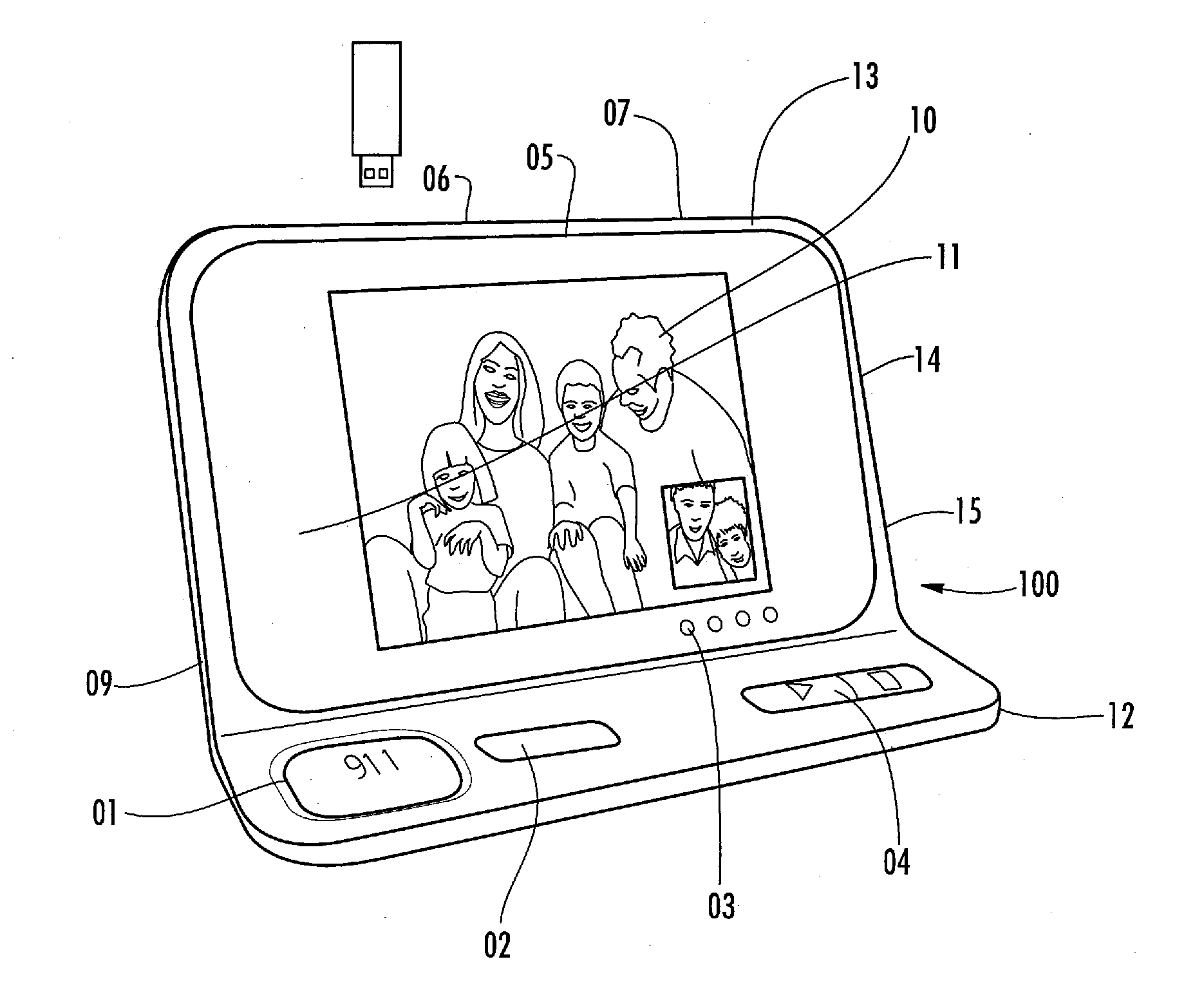
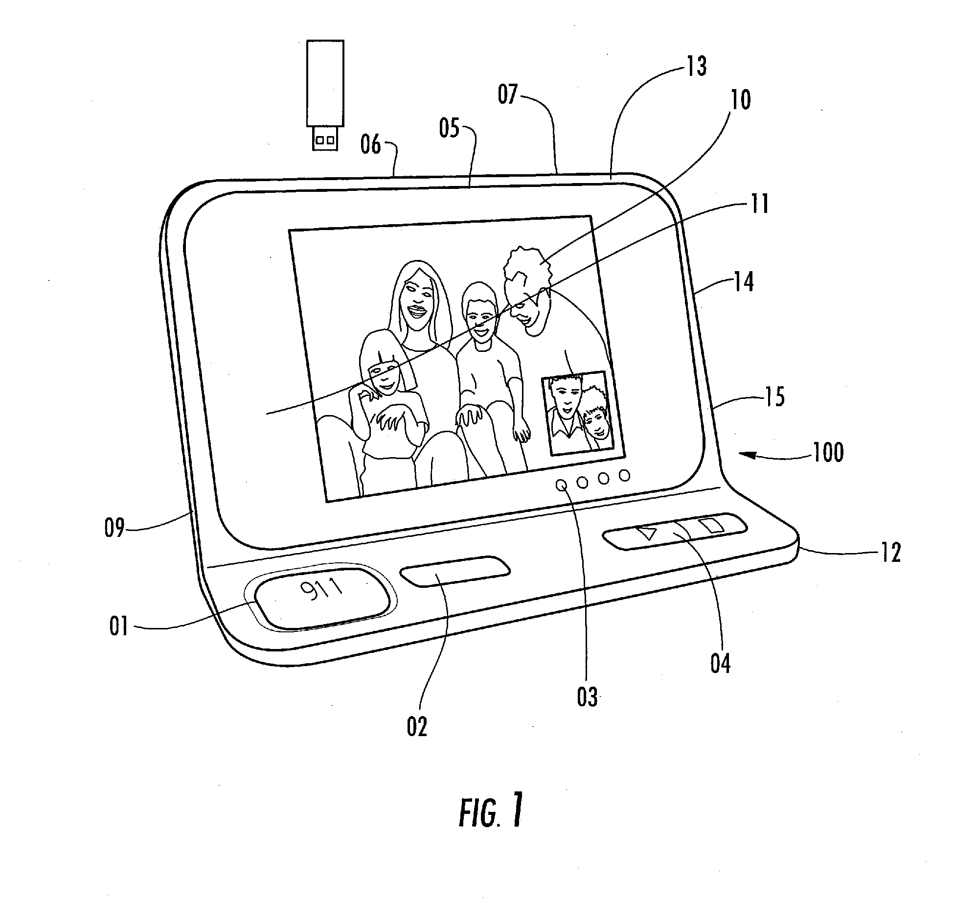
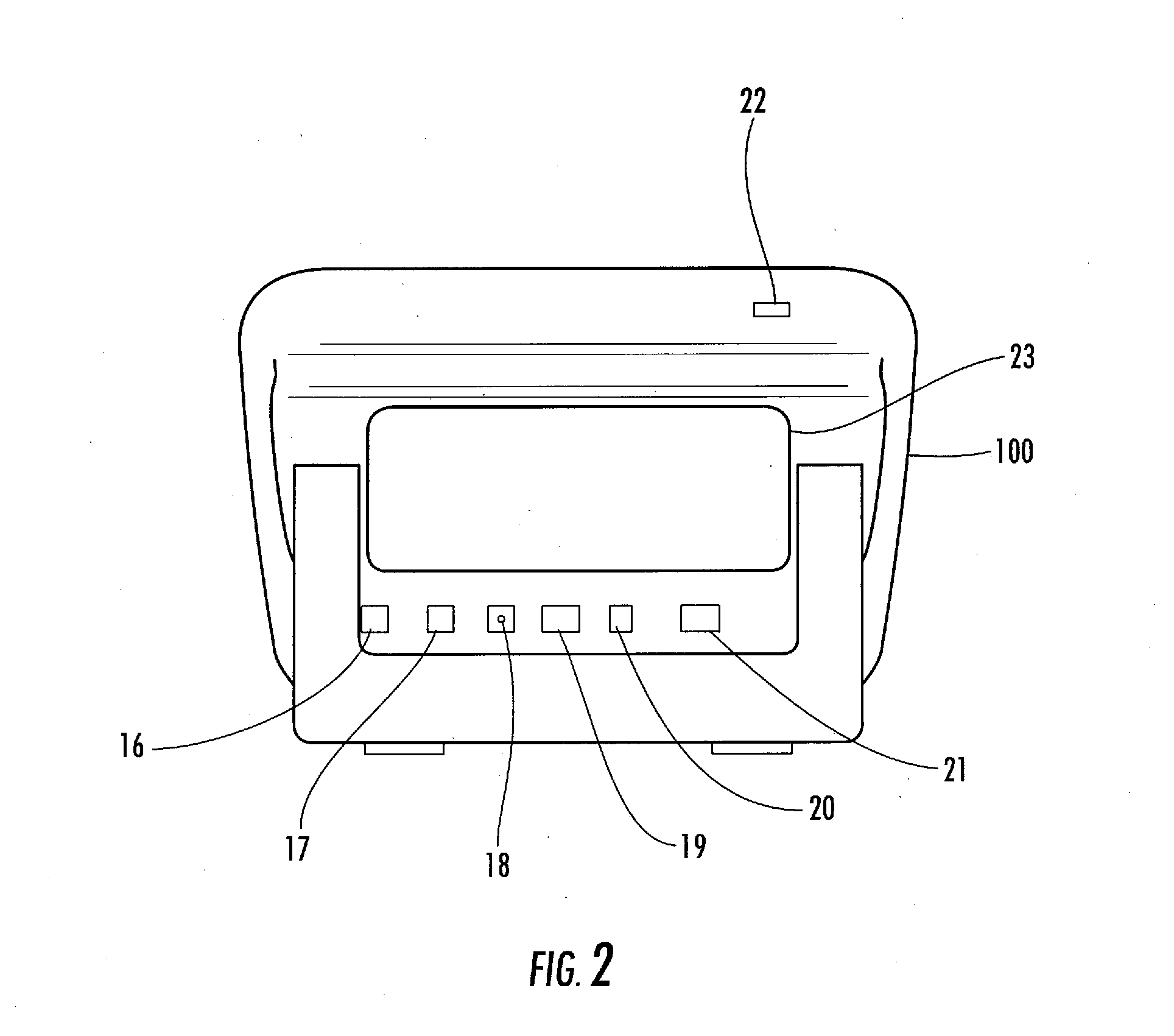
Critical health information profile and emergency communication system

a technology of critical health information and emergency communication system, applied in the field of emergency communication, can solve the problems of no known system that can access the emergency system directly, loss of life, etc., and achieve the effect of reducing costs and reducing costs

Active Publication Date: 2012-04-12
MEDSIGN INT CORP
View PDF13 Cites 25 Cited by
  • Summary
  • Abstract
  • Description
  • Claims
  • Application Information

AI Technical Summary

Benefits of technology

[0021]Yet another objective of the instant invention is to provide a system that allows emergency responders the ability to forward the user's critical information profile to the receiving medical center in a seamless fashion, thus creating effectiveness and efficienci

Problems solved by technology

Accidents happen often and without warning, and when they do the speed of response and access of critical user information determines their survivability.
While heart attacks are at the top of the list, strokes, seizures and personal injuries resulting from accidents are also leading causes for loss of life.
While numerous companies have marketed fee-based patient monitoring systems, there are no known systems that can access the 9-1-1 emergency system directly and provide timely critical health information to the first responder without going through a middle-man for patient information.
There are several reasons, but the first is that time is of the essence, and if the information is not in front of them it is considered useless.
The second most important reason is because ‘a third party’ is involved and the information could be inaccurate which could create a liability on the responder's part.
However, no known companies have produced an emergency communication system with a digital personal health information subsystem incorporated into it's device that can be acce

Method used


Image

  • Critical health information profile and emergency communication system
  • Critical health information profile and emergency communication system
  • Critical health information profile and emergency communication system

Examples


first embodiment

[0078]Referring to FIGS. 3A-3E, set forth is a transmitter (30) having a Call Button (31) to activate the transmitter and send a signal to the base unit starting the 9-1-1 calling sequence. A Stop Button (32) sends a transmission to the base unit to stop the 9-1-1 call. Holding the button for five seconds, along with the Stop button on the base unit digitally ‘pairs’ the two devices to each other. An LED Signal Indicator (33) indicates that the device is active and can be tested by pressing either the Call or Stop button. The transmitter (30) can be attached to a line (35) for hanging about the User's neck, or attached to a wrist band (36) where it can be worn like a bracelet. Alternative connection attachments allow coupling to a ring (37) for use as a key chain or a clip (38) for attachment to a belt. The transmitter includes a USB connection port (39) allowing storage of medical information. The device can be in the form of a pendant or a watch. Its operation can be activated by ...

second embodiment

[0079]Referring to FIGS. 4A-4E, set forth is a transmitter (40) having a Call Button (41) to activate the transmitter and send a signal to the base unit starting the 9-1-1 calling sequence. A Stop Button (42) sends a transmission to the base unit to stop the 9-1-1 call. Holding the button for five seconds, along with the Stop button on the base unit digitally ‘pairs’ the two devices to each other. An LED Signal Indicator (43) indicates that the device is active and can be tested by pressing either the Call or Stop button. The transmitter (40) can be attached to a line (45) for hanging about the User's neck, or attached to a wrist band (46) where it can be worn like a bracelet. Alternative connection attachments allow coupling to a ring (47) for use as a key chain or a clip (48) for attachment to a belt. The transmitter includes a USB connection port (49) allowing storage of medical information.

third embodiment

[0080]Referring to FIGS. 5A-5E, set forth is a transmitter (50) having a Call Button (51) to activate the transmitter and send a signal to the base unit starting the 9-1-1 calling sequence. A Stop Button (52) sends a transmission to the base unit to stop the 9-1-1 call. Holding the button for five seconds, along with the Stop button on the base unit digitally ‘pairs’ the two devices to each other. An LED Signal Indicator (53) indicates that the device is active and can be tested by pressing either the Call or Stop button. The transmitter (50) can be attached to a line (55) for hanging about the User's neck, attached to a ring (57) for use as a key chain or a clip (58) for attachment to a belt. The transmitter includes a USB connection port (59) allowing storage of medical information.


PUM


Abstract

A microprocessor-based emergency response communication system used to call and communicate with the 9-1-1 operator and also allows emergency responder's immediate access to a user's Critical Health Information Profile stored in the device at the point and location of crisis. The device is used to create individual Critical Health Information Profiles which is Health Level-7 compliant enabling it to seamlessly communicate with major hospital networks worldwide. This functional capability provides a system that can retrieve and transmit user-stored personal and health information by emergency responders at the point of care. The emergency responder can access the customer's Critical Health Information Profile database, review the data for pertinent information and then transmit that data to a designated receiving hospital or medical center. The device provides an electronic means of dialing and communicating directly with the 9-1-1 operator. A wireless remote transmitter unit can be activated from the wireless transmitter or the base unit to dial and connect with the 9-1-1 operator, broadcast a canned message with or without a personal-recorded message, and personally communicate with the 9-1-1 operator through a two-way speakerphone system. The device contains software enabling the user and medical personnel the ability to input, store, retrieve and analyze the user's vital sign data and other pertinent health information.

Description

CROSS REFERENCE TO RELATED APPLICATIONS[0001]This application claims benefit of the filing date of U.S. Provisional Patent Application No. 61 / 391,653, filed on Oct. 10, 2010, the contents of which are herein incorporated by reference.FIELD OF THE INVENTION[0002]The invention is directed to the field of emergency communications and, in particular, to a communication system that facilitates an emergency response and provide the health information profile of a patient to a first responder.BACKGROUND OF INVENTION[0003]Accidents happen often and without warning, and when they do the speed of response and access of critical user information determines their survivability. The sooner that a first responder can treat an emergency situation, and the more information the first responder has access to regarding the person who is in a crisis situation, the better the chance of minimizing the risk of permanent damage, disability or even death.[0004]Each year, about 1.1 million Americans suffer a...

Claims


Application Information

Patent Timeline
IPC IPC(8): H04M11/04
CPCG06F19/322G06F19/3418G06F19/323G16H10/60G16H10/65G16H40/67
Inventor CONROY, THOMAS M.
Owner MEDSIGN INT CORP
Why Eureka
Try Eureka