
Algorithm for photonic needle console

a technology of needle console and algorithm, applied in the field of medical interventions, can solve the problem that the tissue recognition accuracy of tissue classification algorithms might not be good enough, and achieve the effect of increasing the recognition rate of tissue classification algorithms and enhancing the guiding procedur

Active Publication Date: 2012-04-12
KONINKLIJKE PHILIPS ELECTRONICS NV
View PDF4 Cites 17 Cited by
  • Summary
  • Abstract
  • Description
  • Claims
  • Application Information

AI Technical Summary

Benefits of technology

The patent text describes a system for accurately optical tissue characterization by using different types of photonic needles with different outer diameters and lengths. The system includes a needle device with an authentication means identifying the type of needle device, and a console including a plurality of algorithms for processing data from the needle device. The system can be used in different interventions and can also include an imaging modality for non-invasive acquisition of image data of a region of interest. The technical effect of the invention is to enhance the recognition rate of tissue classification algorithms and improve the accuracy of optical tissue characterization.

Problems solved by technology

Although it is possible to extract the spectral contributions of several types of tissue from a measured wavelength spectrum, the tissue recognition accuracy of tissue classification algorithms might not be good enough, especially if the number of different types of tissues to classify is very large or one tissue compound is predominantly present.

Method used


Image

  • Algorithm for photonic needle console
  • Algorithm for photonic needle console
  • Algorithm for photonic needle console

Examples


Embodiment Construction

[0046]In the following sections, the claimed invention will be explained in more detail with respect to special embodiments referring to the accompanying drawings.

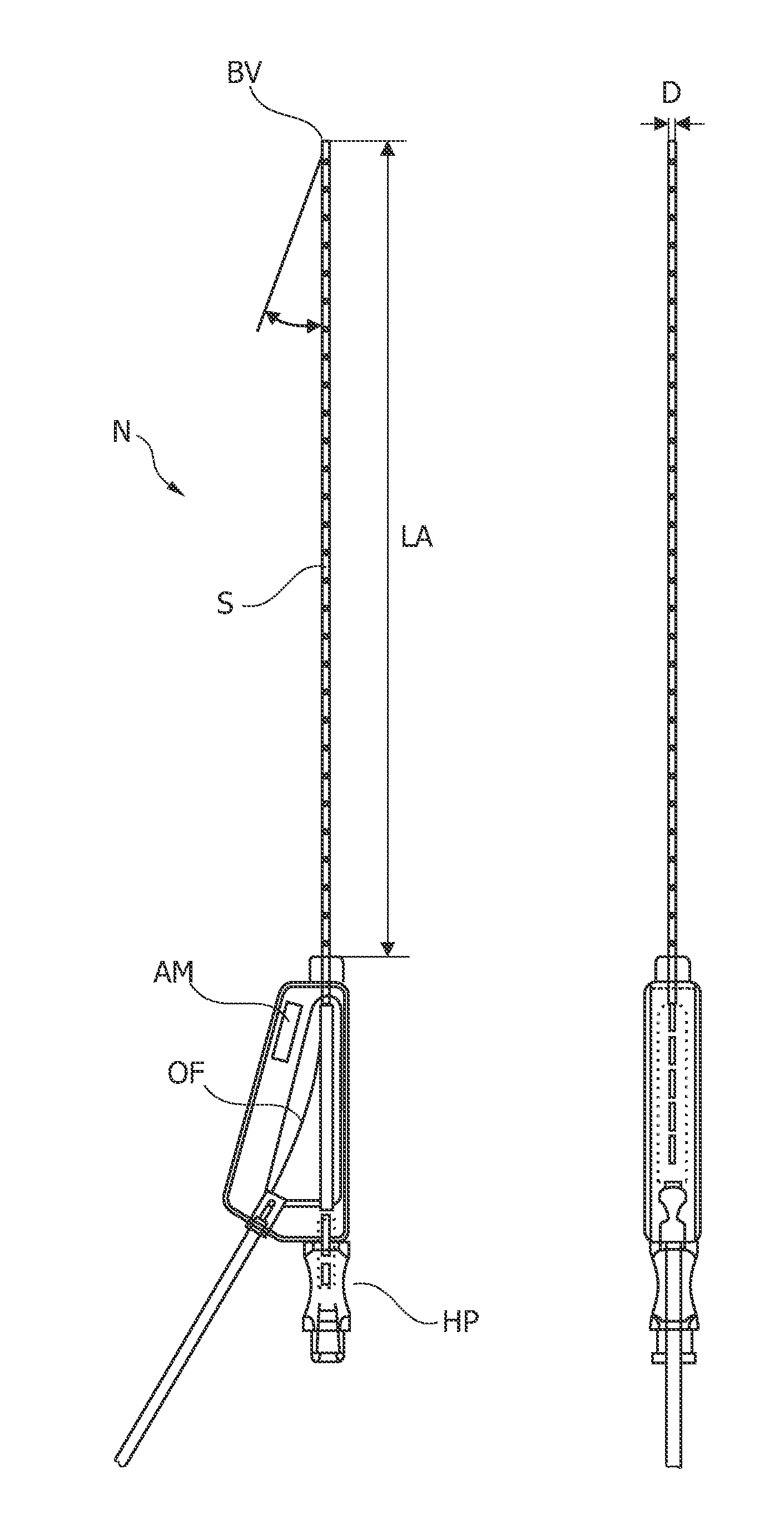
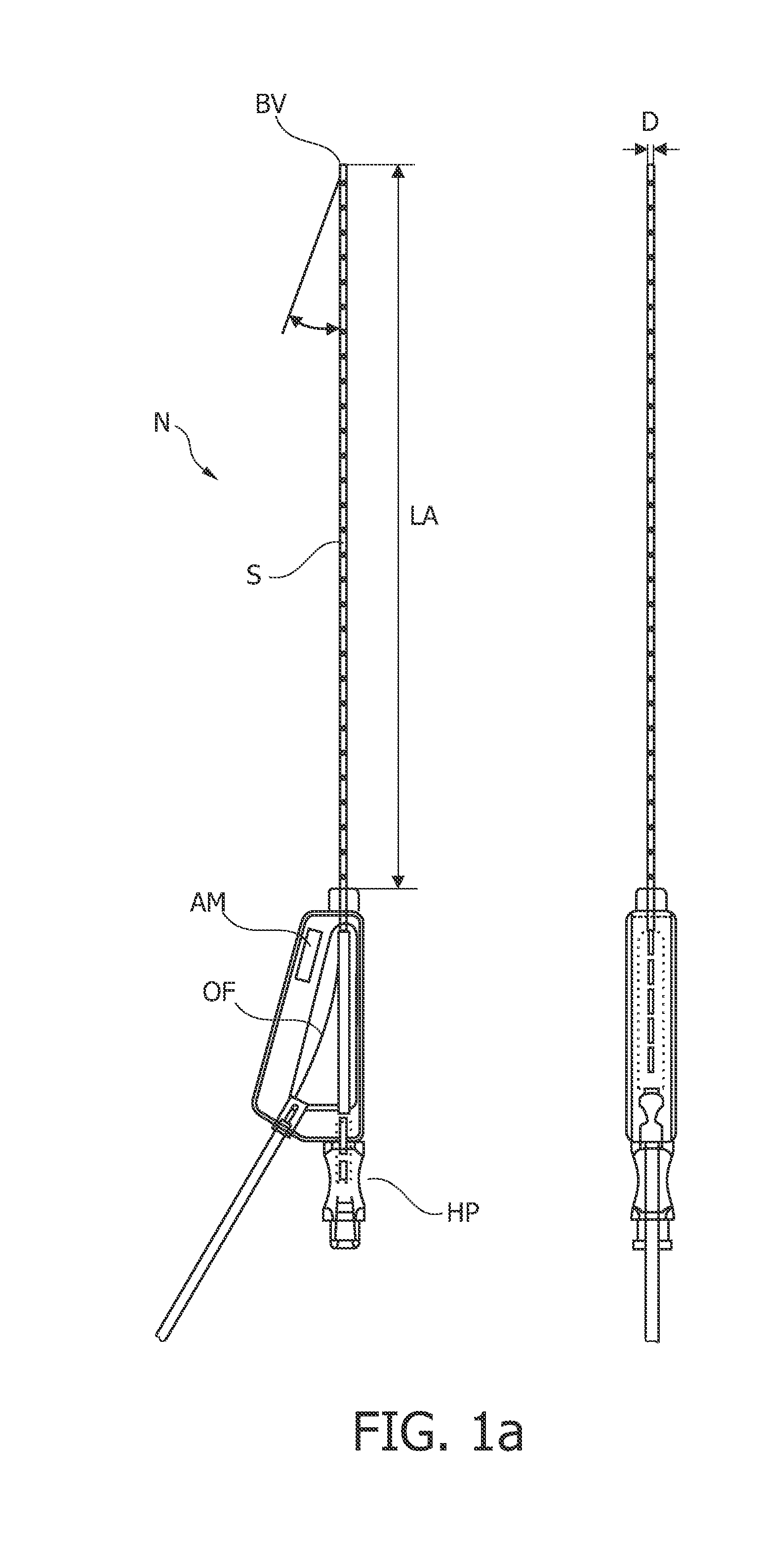
[0047]In FIG. 1a, a side view and a top view of a photonic needle N is shown which can advantageously be applied for minimally invasive tissue inspection by means of optical spectroscopy. As depicted in this figure, such a photonic needle typically comprises a hollow cylindrical shaft S with a bevel BV at its tip portion, a light-guiding means given by an optical fiber OF, integrated into the hollow shaft, and a holder part HP. The optical fiber OF runs from the distal end of the needle, given by the surface of bevel BV, through the interior of the hollow shaft S to the holder part HP and may pass through an opening of the holder part HP out of the needle.

[0048]Furthermore, in FIG. 1a is indicated an authentication means AM. It is noted that the authentication means may be electronically, mechanically or optically readable...


PUM


Abstract

Needles are widely used in interventional radiology. Each medical application requires a specific needle type. The same holds for the photonic needles which analysis depends on the type of application the clinician aims for. Therefore, it is relevant to have the X-ray machine recognize the type of needle that is being used and to load the required software for the tissue analysis. It is therefore proposed to have a data link established between the imaging modality used for the acquisition of the patient anatomy (X-ray, CT, MR or US) and the system that processes optical data from the needle, so that the information from this imaging modality can be used to guide the processing. In a preferred embodiment the selection is made by reading out the code present in the disposable needle when it is connected to the console.

Description

FIELD OF THE INVENTION[0001]The present invention relates to the field of medical interventions and especially to the field of percutaneous needle-mediated interventions. In particular, the invention refers to a system for tissue inspection, including a needle device and a console, as well as to a software program adapted to be executed on the console.TECHNOLOGICAL BACKGROUND[0002]Percutaneous needle-mediated interventions are widely used for diagnosing a large variety of diseases where biopsies of tissue are taken for tissue examination. In oncology, for example, biopsies of a pathological tissue region of interest are taken in order to examine whether this tissue is cancerous or not and, in case of a localized tumor, to determine whether the tumor is benign or malignant. A typical application scenario is mammographic visualization of cancerous tumors within a female patient's breast. In order to accurately diagnose and effectively treat the cancer, it may be necessary for a surgeo...

Claims


Application Information

Patent Timeline
Patent Type & Authority Applications(United States)
IPC IPC(8): A61B5/1455A61B5/055A61B5/05G16H30/20G16H30/40G16H50/20
CPCA61B5/0066G06F19/3406A61B5/0075A61B5/0084A61B5/0091A61B5/14503A61B5/6848A61B5/7435A61B5/7475A61B6/467A61B6/469A61B6/545A61B8/0833A61B8/467A61B8/585A61B17/3401A61B17/3403A61B19/5244A61B2017/00199A61B2017/00225A61B2019/442A61B2019/444A61B2019/448A61B2019/5238A61B2019/5255A61B2019/5408A61B2019/5445A61B2562/08G06F19/321A61B5/0071A61B8/461A61B8/469A61B90/96A61B2034/2055A61B2090/3945A61B34/20A61B2090/376A61B90/92A61B90/98A61B2090/3908G16H40/63G16H30/20G16H50/20G16H30/40
Inventor NACHABE, RAMIHENDRIKS, BERNARDUS HENDRIKUS WILHELMUSBRAUN, AUGUSTINUS LAURENTIUSVAN DER VOORT, MARJOLEINDESJARDINS, ADRIENBABIC, DRAZENKOMIHAJLOVIC, NENAD
Owner KONINKLIJKE PHILIPS ELECTRONICS NV
Learn More