System and method for determining compression device degradation

a compression device and degradation technology, applied in the direction of machines/engines, electric control, instruments, etc., can solve the problems of oil fed to the turbocharger bearing, affecting engine operation, compression device degradation,

Inactive Publication Date: 2012-04-12
GE GLOBAL SOURCING LLC
View PDF17 Cites 10 Cited by
  • Summary
  • Abstract
  • Description
  • Claims
  • Application Information

AI Technical Summary

Problems solved by technology

However, compression device degradation creates various issues that affect engine operation.
For example, if a turbocharger fails and stops spinning due to bearing seizure, oil fed to a turbocharger bearing leaks into an intake manifold of ...

Method used


Image

  • System and method for determining compression device degradation
  • System and method for determining compression device degradation
  • System and method for determining compression device degradation

Examples


Embodiment Construction

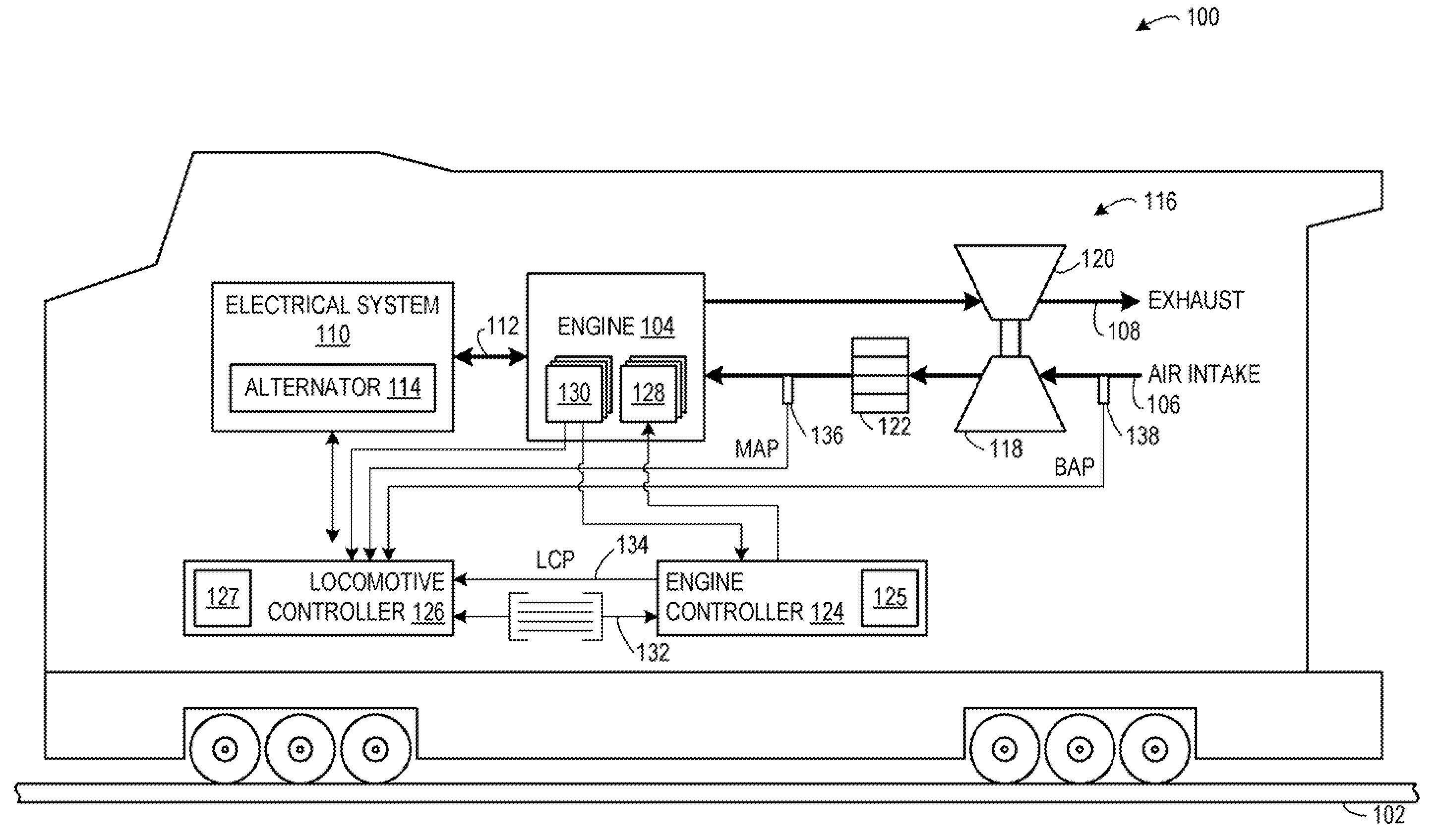
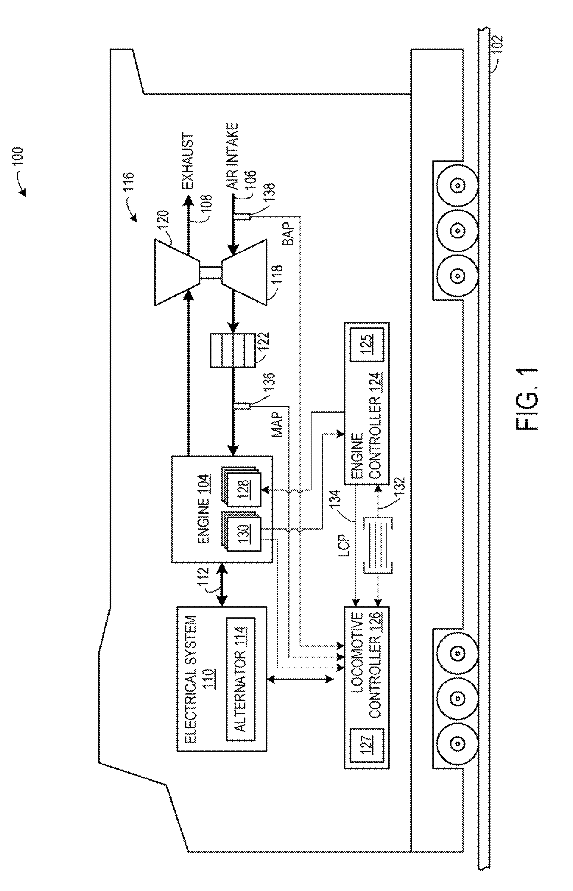
[0011]A stationary power plant, ship, off-highway vehicle, rail vehicle (such as a locomotive) or other such systems include a forced-induction internal combustion engine that receives air from a compression device, such as a turbocharger. An example embodiment of a rail vehicle, as illustrated in FIG. 1, includes a controller to monitor and control operation of various components of the rail vehicle. For example, the controller is configured to monitor performance of a compression device, determine if the compression device has degraded based on the performance, and adjust operation based on the determination of compression device degradation.

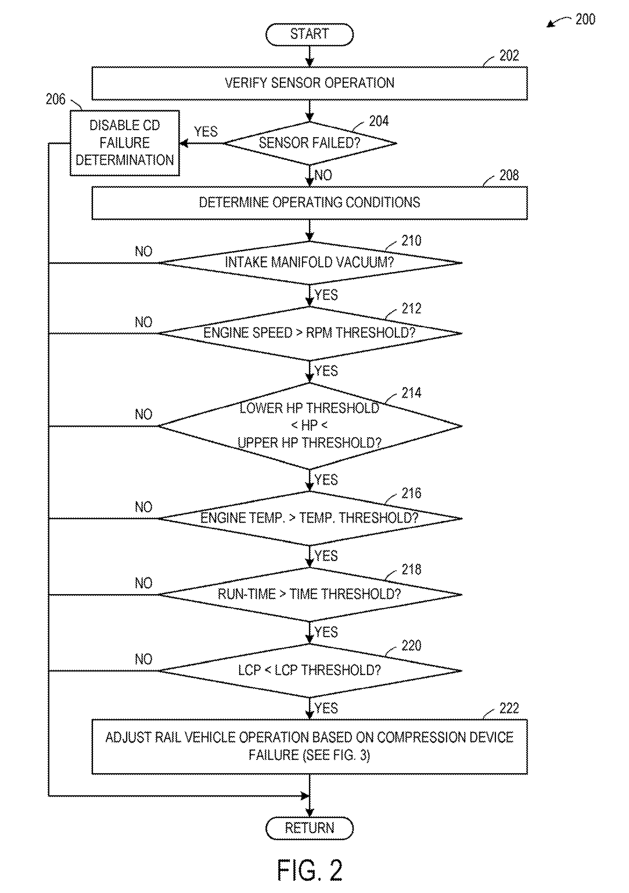
[0012]FIG. 2 shows an example embodiment of a method for determining if a compression device of an engine has degraded based on different operating conditions. As an example, a determination of compression device degradation is based on a pressure difference across a compressor of the compression device during one or more designated operating ...


PUM


Abstract

Systems and methods for determining compression device degradation of an engine of a rail vehicle are provided. In one embodiment, a rail vehicle system includes an engine, an air-intake passage coupled to the engine, a compression device including a compressor positioned along the air-intake passage, a barometric air pressure sensor for measuring a barometric air pressure upstream of the compressor, a manifold air pressure sensor for measuring a manifold air pressure downstream of the compressor, and a controller configured to adjust a rail vehicle operating parameter responsive to a determination of compression device degradation based on a negative pressure differential between the manifold air pressure and the barometric air pressure during a designated operating condition.

Description

FIELD[0001]The subject matter disclosed herein relates to determining if a compression device of an engine of a vehicle has degraded.BACKGROUND[0002]A compression device, such as a compressor of a turbocharger, is implemented with an internal combustion engine to compress intake air, and thereby increase air charge density entering cylinders of the engine. The increased air charge density enables power generated from combustion in the engine cylinders to be increased, while maintaining acceptable air-fuel ratio limits and other operating parameters to reduce emissions.[0003]However, compression device degradation creates various issues that affect engine operation. For example, if a turbocharger fails and stops spinning due to bearing seizure, oil fed to a turbocharger bearing leaks into an intake manifold of the engine. As the engine continues to operate, the oil accumulating in the intake manifold seeps into cylinders of the engine. The introduction of engine oil into the cylinder...

Claims


Application Information

Patent Timeline
IPC IPC(8): F02D28/00
CPCF02D28/00F02D41/0007Y02T10/144F02D41/22F02D2200/0406F02D41/042F02D2200/703Y02T10/12
Inventor NISTLER, PAUL GERARDMISCHLER, JAMES ROBERTHENRY, LUKEGRAY, WILLIAM
Owner GE GLOBAL SOURCING LLC
Why Eureka
Try Eureka