Plastic Pipe with Bell

a plastic pipe and bell technology, applied in the field of plastic pipe bell design, can solve the problems of slow pipe extrusion process, complicated process, slow pipe extrusion speed of corrugator, etc., and achieve the effects of reducing deformation, increasing hoop or circumferential stiffness, and high strength

Inactive Publication Date: 2012-04-19
TOLIVER TIMOTHY +2
View PDF6 Cites 3 Cited by
  • Summary
  • Abstract
  • Description
  • Claims
  • Application Information

AI Technical Summary

Benefits of technology

[0012]A multi-layer bell is formed from the outer shell of a multi-layer pipe in a secondary process, thereby allowing the extrusion process to be conducted at normal speeds. The bell is designed with increased hoop or circumferential stiffness to alleviate deformation during the installation process. This invention may be used for dual wall, triple wall, or other multiple layer pipes. The bell design may include a strain limiting membrane mechanically secured between the outer shell extrusion layer and the inner liner extrusion layer, thereby enabling the use of a wider range of high strength membrane materials that are not necessarily compatible with the base resin of the pipe. This invention allows the extrusion process to be in its simplest form, with no adjustments to the corrugator or extruder speeds in an effort to control bell wall thickness. Production speeds may be increased by allowing a thinner outer shell extrusion layer at the pipe bell. The present invention may be used in conjunction with existing pipe extruding technology, minimizing the capital investment and reducing complexity of the pipe corrugating process as compared to current multi-layer bell forming technologies performed as part of the pipe extrusion corrugating process.

Problems solved by technology

Single layer bell extrusion processes often include complicated corrugators and extruder controls to help thin or thicken the bell, slowing down the pipe extrusion process.
This process is complicated and is also known to slow down the extrusion speed of the corrugators.
Bell design involves several issues which have caused problems in the past.
Undulations or irregularities have been known to cause problems of gasket rolling when a bell and spigot joint are assembled, as the gasket may be caught on the reinforcing ribs.
It is well known that plastic materials can have numerous variables affecting the shrinkage rates during processing.
In both of the known methods of forming an inline bell discussed above, the sealing surface of the inner bell is subject to the shrinkage variability.
This can cause significant dimensional control issues.
For example, rapid cooling of the bell may create internal thermal stresses which may result in deformation.
Differential deformation between the bell and spigot of the pipe joint may also result in leakage of a pipe joint.
Bell expansion caused by sustained internal hydraulic pressure, for example, may result in loss of gasket seating pressure and of a water tight seal.

Method used


Image

  • Plastic Pipe with Bell
  • Plastic Pipe with Bell
  • Plastic Pipe with Bell

Examples


Embodiment Construction

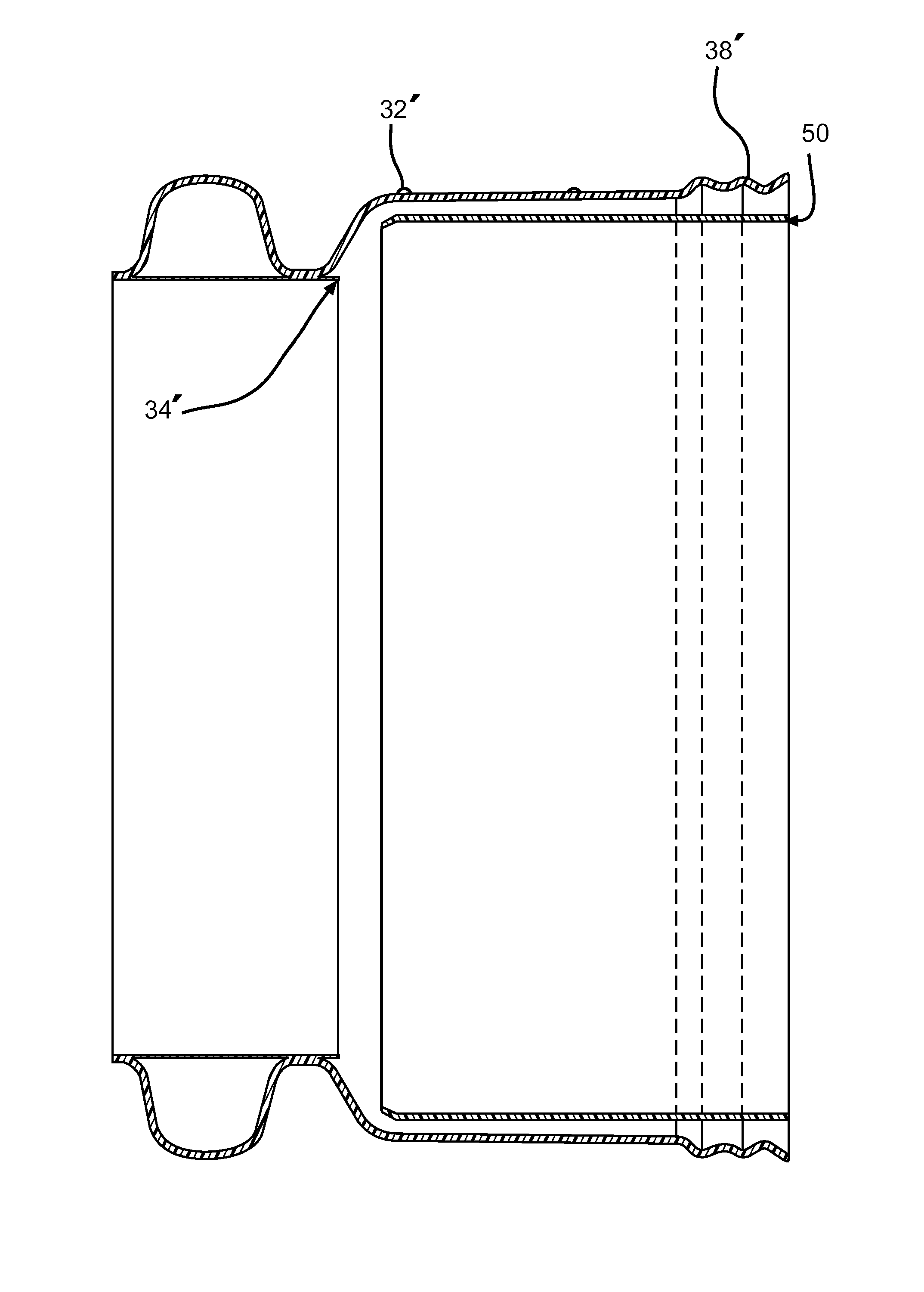
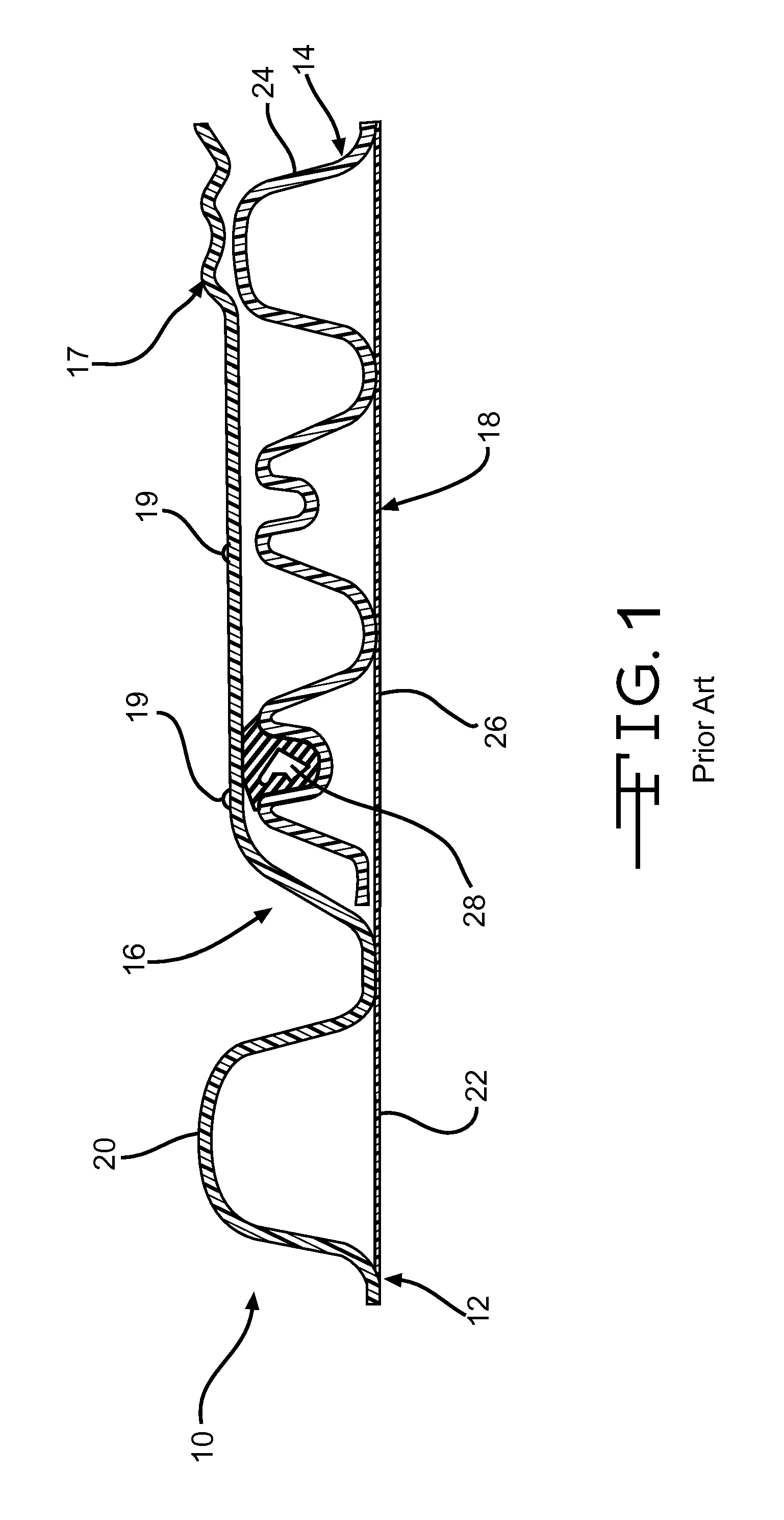
[0019]FIG. 1 shows a typical multi-layer extruded plastic pipe bell and spigot joint 10. The watertight joint is formed from two pipe sections 12, 14 having a bell 16 and spigot 18, respectively. Bell pipe 12 includes an outer shell 20 and an inner liner 22. A bell 16 is formed from the outer shell extrusion layer. The bell 16 includes annular stiffening ribs 17 near the pipe end to maintain roundness. The bell 16 also includes annular stiffening ribs 19 on its outer surface which are relatively small to avoid deforming the inner surface of the bell. Spigot pipe 14 includes an outer shell 20 and an inner liner 26. A hollow polyisoprene or thermoplastic elastomer gasket 28 provides a watertight seal between the bell and spigot. When assembled, the inner layers 22 and 26 preferably abut to provide a smooth inner surface, but this is not essential for most applications.

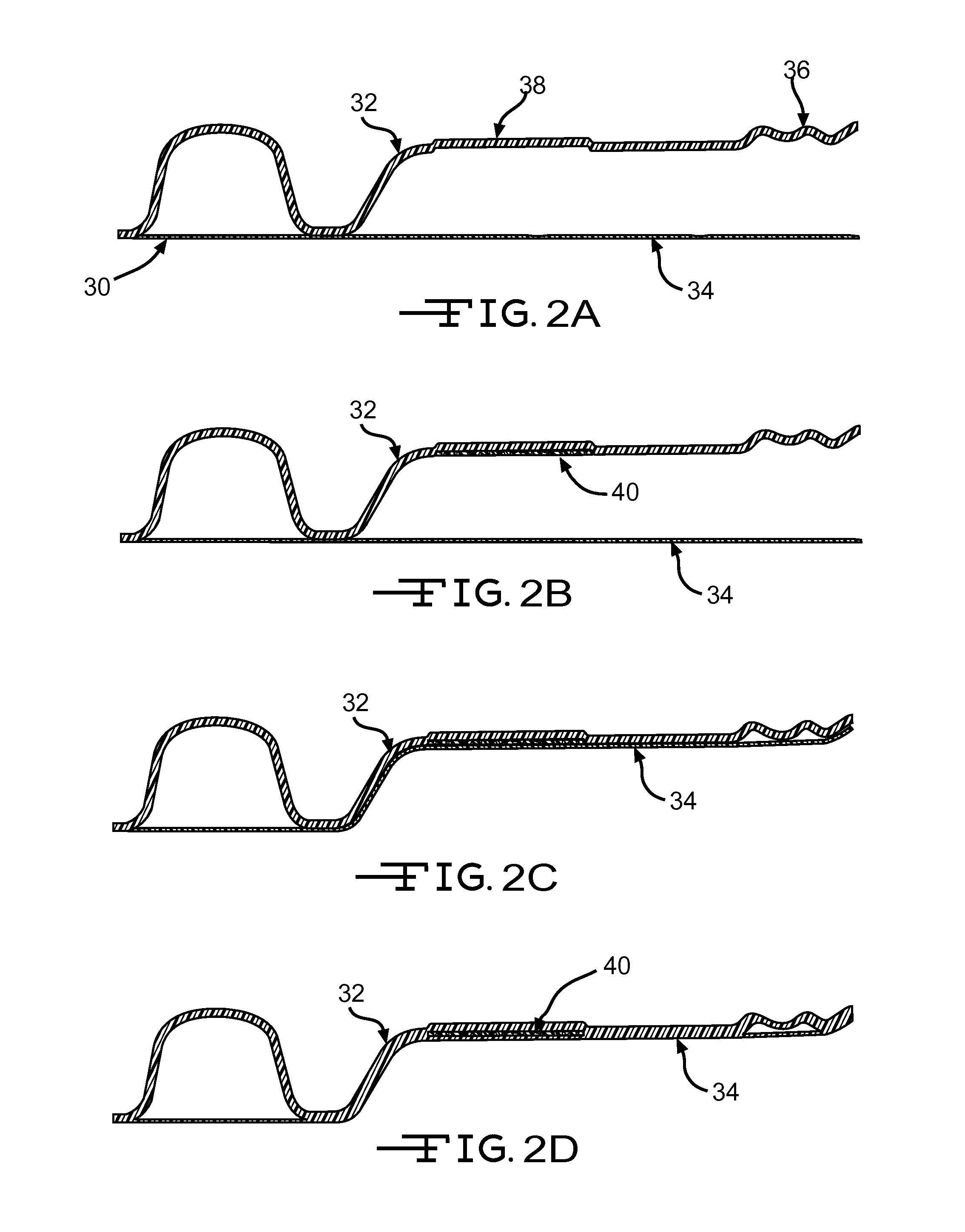
[0020]Referring to FIG. 2A, a two-layer corrugated pipe 30 having an outer layer 32 fused to an inner liner 34 is extr...


PUM

PropertyMeasurementUnit
thicknessaaaaaaaaaa
thicknessaaaaaaaaaa
diameteraaaaaaaaaa

Abstract

A multi-layer bell is formed from the outer shell of a multi-layer pipe in a secondary process, thereby allowing the extrusion process to be conducted at normal speeds. The bell may include a strain limiting membrane fused or mechanically secured between the outer shell extrusion layer and the inner liner extrusion layer, increased hoop or circumferential stiffness. This invention allows the extrusion process to be in its simplest form, with no adjustments to the corrugator or extruder speeds.

Description

CROSS-REFERENCE TO RELATED APPLICATIONS[0001]This application claims the benefit of U.S. Provisional Application No. 61 / 186,871, filed Jun. 14, 2009, the disclosure of which is incorporated herein by reference.FIELD OF THE INVENTION[0002]This invention relates in general to plastic pipe, and more particularly to bell designs for plastic pipe and methods of making bell designs for plastic pipe.BACKGROUND OF THE INVENTION[0003]Bell and spigot joints are commonly used to join pipes, including extruded plastic pipes. Bell and spigot joints typically have three components; a bell on an end of a pipe, a spigot on an end of another pipe, and a gasket. These systems typically form a water tight joint.[0004]Typical extruded multi-wall pipe includes a corrugated layer made using an extrusion process including corrugators. Bell and spigot joints are formed during the extrusion process using pipe corrugators incorporating pipe molds and a bell blocks. For example, see U.S. Pat. No. 5,405,569. T...

Claims


Application Information

Patent Timeline
Patent Type & Authority Applications(United States)
IPC IPC(8): F16L9/12B32B38/00B32B37/12B23P19/00B32B37/14B29C48/30
CPCB29C47/0023Y10T29/49817B29C47/126B29C49/0021B29C57/02B29C65/02B29C65/48B29C2791/006B29D23/003B29K2023/065B29K2023/12B29K2027/06B29K2105/12B29L2016/00B29L2023/22B29L2031/24B29L2031/605F16L25/0054B29C47/021B29C47/065Y10T156/1028B29C47/0033B29C48/303B29C48/09B29C48/13B29C48/21B29C48/151B29C48/07B29C49/0025
Inventor TOLIVER, TIMOTHYKIME, TONYKOSSNER, HUBERT
Owner TOLIVER TIMOTHY
Why Eureka
Try Eureka