Systems and methods for heat transfer utilizing heat exchangers with carbon nanotubes

a technology of carbon nanotubes and heat exchangers, applied in the field of heat exchangers, can solve the problems of time-consuming and cost-intensive techniques for the fabrication of microchannels, and the disadvantage of added pressure drop

Inactive Publication Date: 2012-04-19
RICE UNIV
View PDF20 Cites 40 Cited by
  • Summary
  • Abstract
  • Description
  • Claims
  • Application Information

AI Technical Summary

Benefits of technology

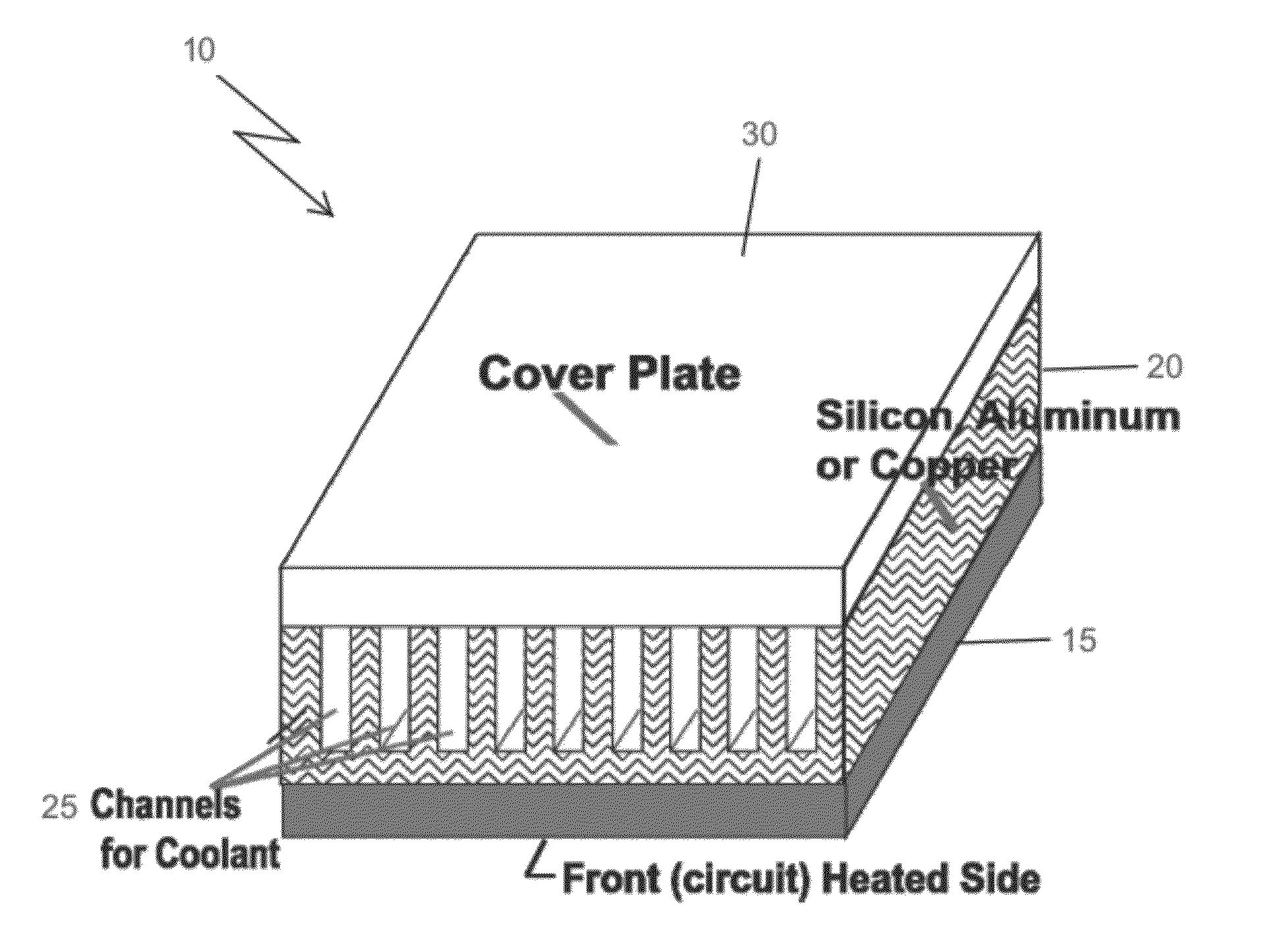
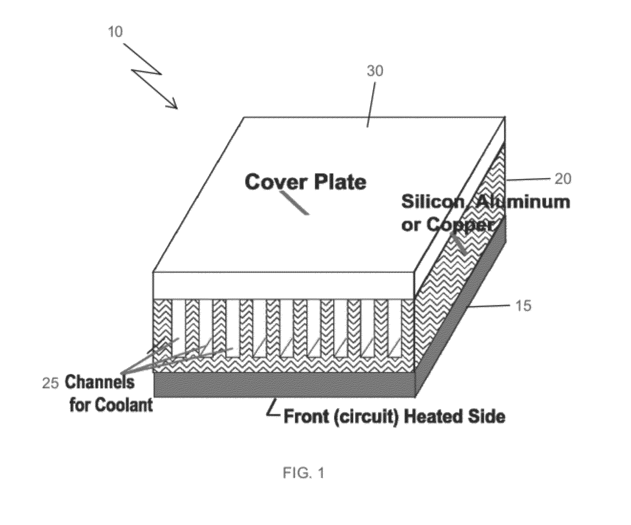
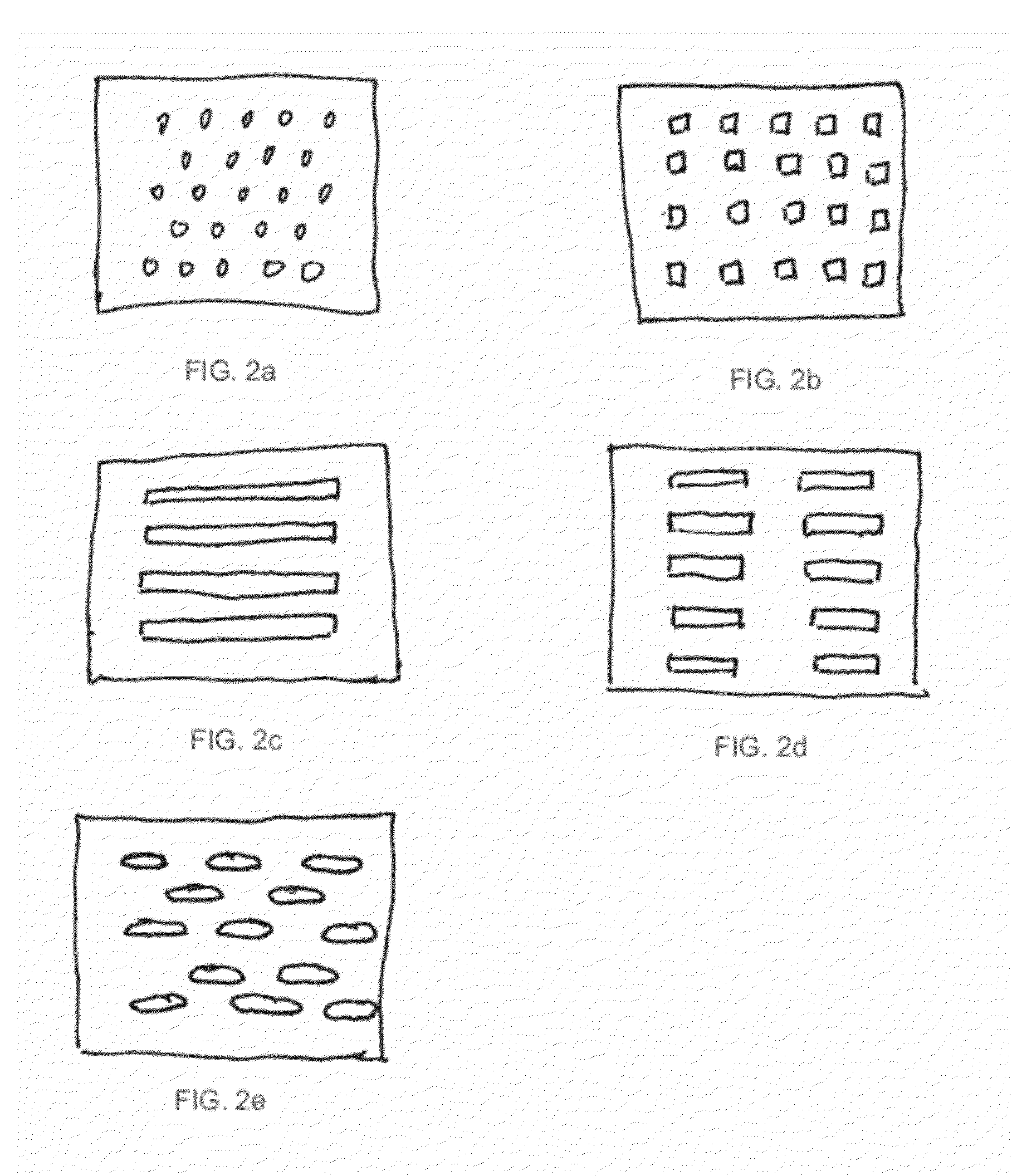
[0010]The nanostructures may cover entire portions of one or more channel surfaces, or the nanostructure may be arranged into bundles providing a desired pattern. Further, a working fluid, such as water, a nanofluid, or a dielectric fluid, passes through the channels to aid heat transfer.

Problems solved by technology

In addition, the fabrication of microchannels would require techniques that are time consuming and cost intensive.
While these methods increase heat transfer, due to increased surface area, better flow mixing, and an increased heat transfer coefficient, they also had the disadvantage of added pressure drop.

Method used


Image

  • Systems and methods for heat transfer utilizing heat exchangers with carbon nanotubes
  • Systems and methods for heat transfer utilizing heat exchangers with carbon nanotubes
  • Systems and methods for heat transfer utilizing heat exchangers with carbon nanotubes

Examples


experimental examples

[0041]Additional details about experimental aspects of the above-described studies are discussed below.

NomenclatureAsurface area available for heat transfercpspecific heat at constant pressureLlength of tubing (norprene, manifold)Dhmhydraulic diameter of manifoldDhnhydraulic diameter of norprene tubingffriction factorkthermal conductivity of copper blockkccontraction loss coefficientkeexpansion loss coefficientΔPtotal pressure dropΔPcpressure drop due to contractionΔPchpressure drop across minichannelΔPepressure drop due to expansionΔPmpressure drop through inlet andoutlet manifoldΔPnpressured drop through norprene tubingqheat fluxQheat suppliedΔTtemperature difference betweenthermocouplesTinfluid inlet temperatureToutfluid outlet temperatureTwbase temperatureTbbulk fluid temperatureumfluid velocity through manifoldunfluid velocity through norprenetubingvvolumetric flow rateΔxdistance between thermocouplesin the copper blockGreek Symbolsρdensity

[0042]In order to test the heat transf...


PUM

PropertyMeasurementUnit
hydraulic diameteraaaaaaaaaa
thickaaaaaaaaaa

Abstract

A heat exchanger with mini channels or micro channels provides enhanced heat transfer abilities. One or more surfaces of the channels may be covered with a nanostructure, such as single walled carbon nanotubes or multiwalled carbon nanotubes. The nanostructures may fully cover the entire surface of the channel or a selected surface area of the channel. Further, the nanostructures may be arranged into multiple patterned bundles covering the surface of the channel.

Description

RELATED APPLICATIONS[0001]This application claims the benefit of U.S. Provisional Patent Application No. 61 / 392,568, filed on Oct. 13, 2010, and U.S. Provisional Patent Application No. 61 / 515,398, filed on Aug. 5, 2011, which are incorporated herein by reference.STATEMENT REGARDING FEDERALLY SPONSORED RESEARCH[0002]This invention was made with government support under Grant No. HRD-0450363, awarded by the National Science Foundation. The government has certain rights in the invention.FIELD OF THE INVENTION[0003]This invention relates to a heat exchanger. More particularly, the invention relates to a heat exchanger utilizing carbon nanotubes.BACKGROUND OF INVENTION[0004]Heat exchangers are utilized to provide efficient heat transfer from one medium to another. For example, heat sinks may be utilized on electronic chips to transfer heat generated by the chip to air or another fluid by convection. Heat sinks may have a large surface area to provide efficient heat transfer. For example,...

Claims


Application Information

Patent Timeline
Patent Type & Authority Applications(United States)
IPC IPC(8): F28D1/00B23K26/00B21D53/02
CPCB23K26/38Y10T29/4935B23K26/4075B23K2201/14B23K2201/40B82Y30/00F28D2021/0029F28F3/02F28F21/02F28F2255/20F28F2260/02H01L23/373H01L23/473H01L2924/0002B23K26/388H01L2924/00B23K26/389B23K26/40B23K2101/14B23K2101/40B23K2103/50
Inventor BAYAZITOGLU, YILDIZSHENOY, SUKESH
Owner RICE UNIV
Why Eureka
Try Eureka