Shock absorber

a technology of shock absorber and hygroscope, which is applied in the direction of vibration dampers, mechanical instruments, resilient suspensions, etc., can solve the problems of adding components and complexity, devices and other similar solutions acting as one-way valves thanks to various orifices provided in hygroscopes no longer meet the expectations of the market, etc., and achieves a larger cross section and facilitates the manufacturing of hygroscopes

Inactive Publication Date: 2012-04-19
BWI CO LTD SA
View PDF8 Cites 30 Cited by
  • Summary
  • Abstract
  • Description
  • Claims
  • Application Information

AI Technical Summary

Benefits of technology

[0014]A further advantage of the present invention is that in the end portion of the HRS-tube there is no fluid exit means so that the shock absorber reaches its maximum extension prior to any internal metal to metal contact as some fluid is trapped and can not exit.
[0015]Also, the HRS-tube-in is provided with a chamfer, so the entry of the HRS-piston inside the HRS-tube is guided.
[0016]Another embodiment possible the HRS-tube comprises a plurality of fluid-exit means having different length. This can advantageously facilitate the manufacturing of the HRS-tube.
[0017]Also, the fluid-exit means can comprise at least one groove axially operated in the HRS-wall and extending from the HRS-tube-in toward the inside of the HRS-tube, the groove havi...

Problems solved by technology

This device and other similar solutions acting as one-way valves thanks to various orifices provided ...

Method used


Image

  • Shock absorber
  • Shock absorber
  • Shock absorber

Examples


Embodiment Construction

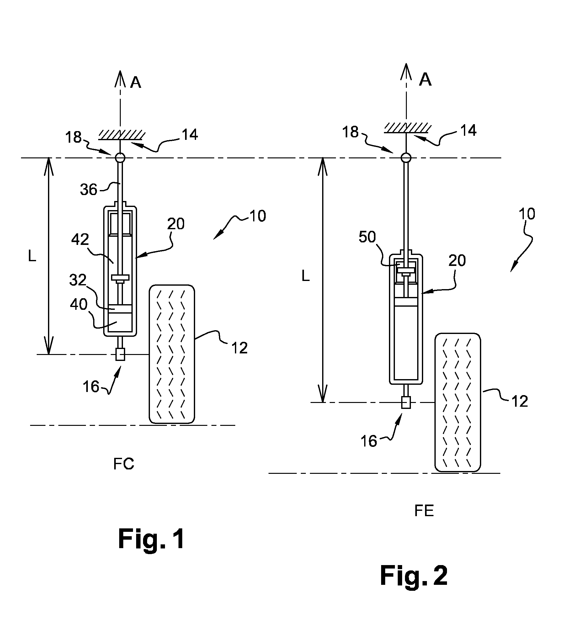
[0042]FIG. 1 and FIG. 2 represent a suspension system of a vehicle 10 comprising a shock absorber 20 joining a wheel knuckle 12 or suspension arm to the car body 14 along an axis A. The shock absorber 20 has an overall length L ranging from a bottom mounting point 16 attached to the suspension arm or to the wheel knuckle 12, to an upper mounting point 18, called body end 18, attached to the car body 14. In FIG. 1, the system is represented in Full Compression FC position, the shock absorber 20 is at its shortest length L the wheel 12 being the closest possible to the car body 14. In FIG. 2 the system is represented in a Full Extension FE position, the shock absorber 20 is at its longest length L the wheel 12 being at the furthest possible distance to the car body 14.

[0043]To ease the description, the axis A is oriented from the wheel 12 toward the car body 14.

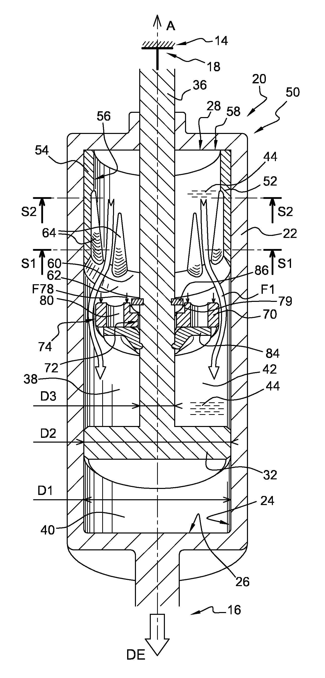
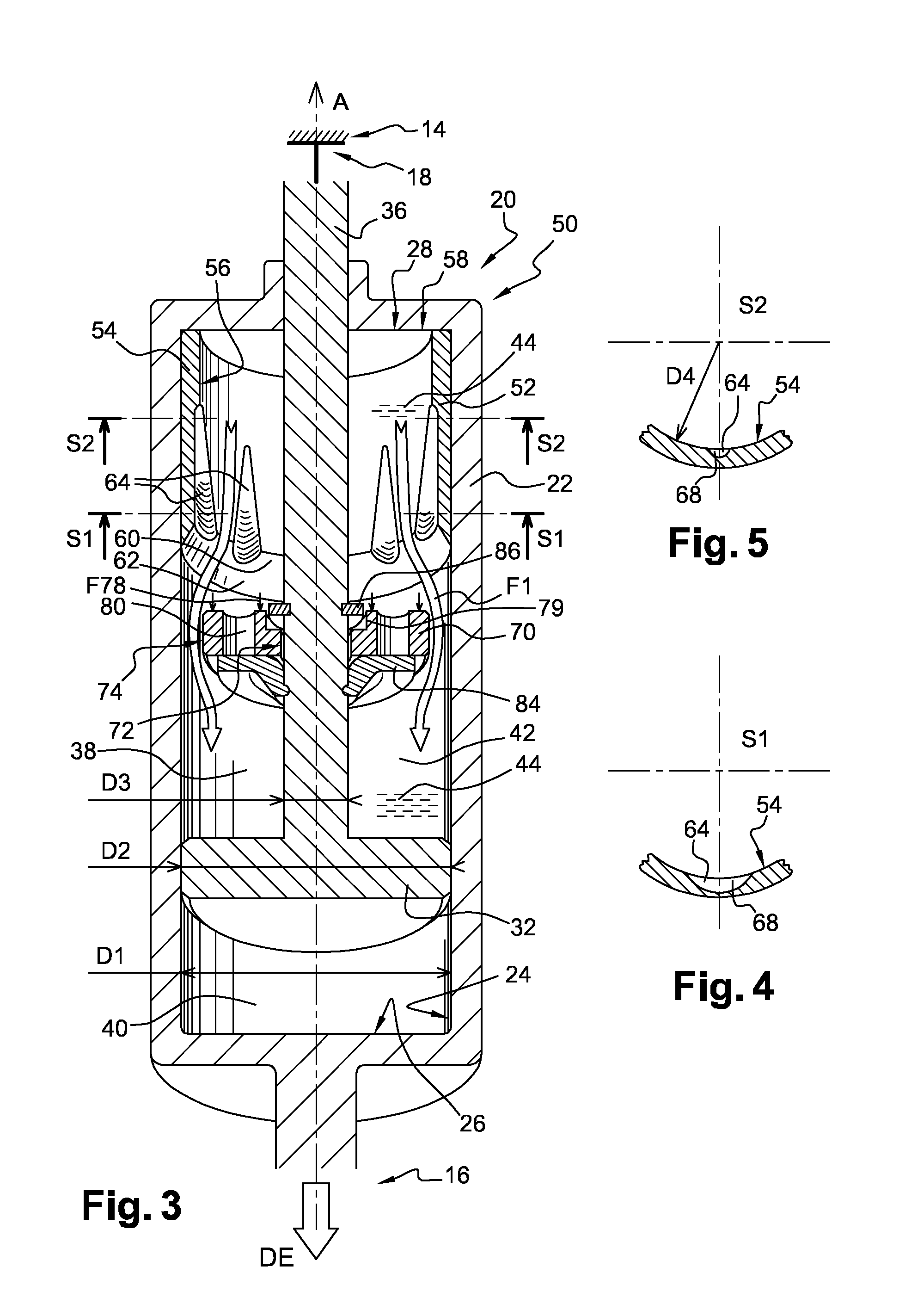
[0044]As generally presented by FIG. 3, the hydraulic shock absorber 20 comprises a main tube 22 in which is axially slidably...


PUM


Abstract

A hydraulic shock absorber comprising a main tube divided, by a piston-rod extending through the extension chamber. The shock absorber is further provided with a hydraulic rebound stop, called HRS fixed in the extension chamber and comprising a HRS-tube restricting the main tube, bottom and an 10 entry. The HRS also has HRS-piston freely slidably mounted on the rod and having a diameter adjusted to the HRS-tube and being provided with at least one fluid-passage substantially axially oriented. The axial displacements of the HRS-piston are limited between a Rebound-stop and a HRS-ring, both fixed to the rod. The fluid-passage is open to a flow of fluid when in abutment against the HRS-ring and being sealed when in abutment against the Rebound-stop. The HRS is further provided with at least one fluid-passage connecting the HRS-chamber to the extension chamber and providing to the fluid a way-out for an exiting flow generating a HRS-damping which is tunable and varies as the HRS-piston penetrates the HRS-tube, their relative position determining the size of the way-out.

Description

TECHNICAL FIELD[0001]The present invention relates to a hydraulic shock absorber that can be used in an automotive vehicle or a motorcycle, and more particularly to a hydraulic rebound stop.BACKGROUND OF THE INVENTION[0002]Hydraulic shock absorbers are conventionally designed such that the damping rate provided by the shock absorber becomes higher at the extreme ends of the rebound and compression strokes. The additional damping provided at the extreme ends prevent an abrupt halt of the piston rod travel as well as jarring metal to metal contact between the various parts in the shock absorber. A variety of mechanisms have been proposed to provide a higher damping rate at the two extreme. For example WO2005 / 106282 proposes a hydraulic rebound stop, called HRS, consisting of a hydraulic damper coaxially assembled inside the extension chamber of the shock absorber and only operating when the shock absorber is reaching full extension. Such device comprises a HRS-tube fixed inside the tu...

Claims


Application Information

Patent Timeline
IPC IPC(8): F16F9/48B60G13/08
CPCB60G13/08F16F9/49F16F9/3465
Inventor KRAZEWSKI, OLAFWIDLA, WALDEMARSLUSARCZYK, PAWEL
Owner BWI CO LTD SA
Why Eureka
Try Eureka