Light source apparatus, image display apparatus and television receiving apparatus

a technology for display apparatus and light source, which is applied in the direction of television systems, lighting support devices, instruments, etc., can solve the problems of limited board distance, inability to combine light source units, and display apparatus of patent document 1 can not solve problems, etc., to enhance the cooling effect of led boards, prevent light leakage, and enhance the quality of light source units and display apparatus

Inactive Publication Date: 2012-04-19
SHARP KK
View PDF0 Cites 24 Cited by
  • Summary
  • Abstract
  • Description
  • Claims
  • Application Information

AI Technical Summary

Benefits of technology

[0071]According to the present invention, it is possible to receive the television broadcasting signal and display the image on the display panel.
[0072]In accordance with the present invention, the light source unit is supported by the support plate to be slidable along the one surface of the support plate. Therefore, it is possible to electrically connect the light source units even when, for example, the distance of boards (light source units) is longer than a predetermined length or shorter than a given length by dimensional error, machining error or the like.
[0073]In accordance with the present invention, the rivet (axial fall preventer) is inserted into the board hole (opening) provided to the LED board and the through hole (opening) provided to the radiator plate (support plate), and the LED board is fixed to the radiator plate. Although tightening force may act on a local area of the LED board when a screw is utilized to fix, acting force on the LED board is distributed by the large diameter head portion of the rivet when the rivet is utilized to fix. Therefore, the LED board is unlikely warped, the contact area of the LED board with the radiator plate becomes larger than the case of fixation with the screw, and it is possible to enhance the cooling effect on the LED board.
[0074]In accordance with the present invention, the rivet (axial fall preventer) can prevent the light leakage caused by the threaded hole (opening). Therefore, it is possible to enhance the quality of light source unit and the display apparatus including the light source unit. Furthermore, it is not required for the prevention of the light leakage caused by the threaded hole (opening) to match the inner diameter of the threaded hole with the outer diameter of the rivet inserted into the threaded hole. Therefore, it is easy to insert the rivet into the threaded hole. In other words, the utilization of the rivet does not degrade the workability for fixing the circuit board to the assist member (support plate). Moreover, after the rivet is fixed, it is not required to seal a gap between the rivet and the circuit board and a gap between the rivet and the assist member. Therefore, it does not increase the number of steps for the manufacturing process and it can avoid the light leakage from an unsealed portion.
[0075]The present invention can provide a light source apparatus that can radiate the heat of a circuit board, even when the circuit board mounting a light emitting element is bent by the rise in its own temperature. In addition, the present invention can provide a light source apparatus that sufficiently radiate the heat of a rectangular circuit board that includes plural light emitting elements arranged in the longitudinal direction and is likely to be bent in the longitudinal direction. In addition, the present invention can provide a light source unit that can easily configure a thermal conductor having a high performance of the thermal conductivity by a carbon-containing sheet applied to another surface of a circuit board. In addition, the present invention can provide a light source apparatus that can easily configure a thermal conductor having a high performance in the thermal conductivity by a carbon-containing paint layer on another surface of a circuit board. In addition, the present invention can provide a display apparatus that includes a light emitting element arranged at a back side of a display unit, and a behind type light source apparatus having a high performance in the radiation.

Problems solved by technology

However, a distance of boards required for the connector is limited.
For example, if the distance of arranged boards is more than a predetermined length or less than an estimated length by dimensional error, machining error or the like, a problem is caused that the light source units cannot be combined together.
The display apparatus of Patent Document 1 cannot solve the problem.
Thus, it may cause a problem that the generated heat expands the board having been fixed to the support plate supporting the board, the board is distorted and the like.
Hence, it may cause a problem that the board tends to be bent.
When the board is distorted or bent, the connection between the board and the support plate may be looseneed and the heat of light source may be radiated insufficiently.

Method used


Image

  • Light source apparatus, image display apparatus and television receiving apparatus
  • Light source apparatus, image display apparatus and television receiving apparatus
  • Light source apparatus, image display apparatus and television receiving apparatus

Examples


embodiment 1-1

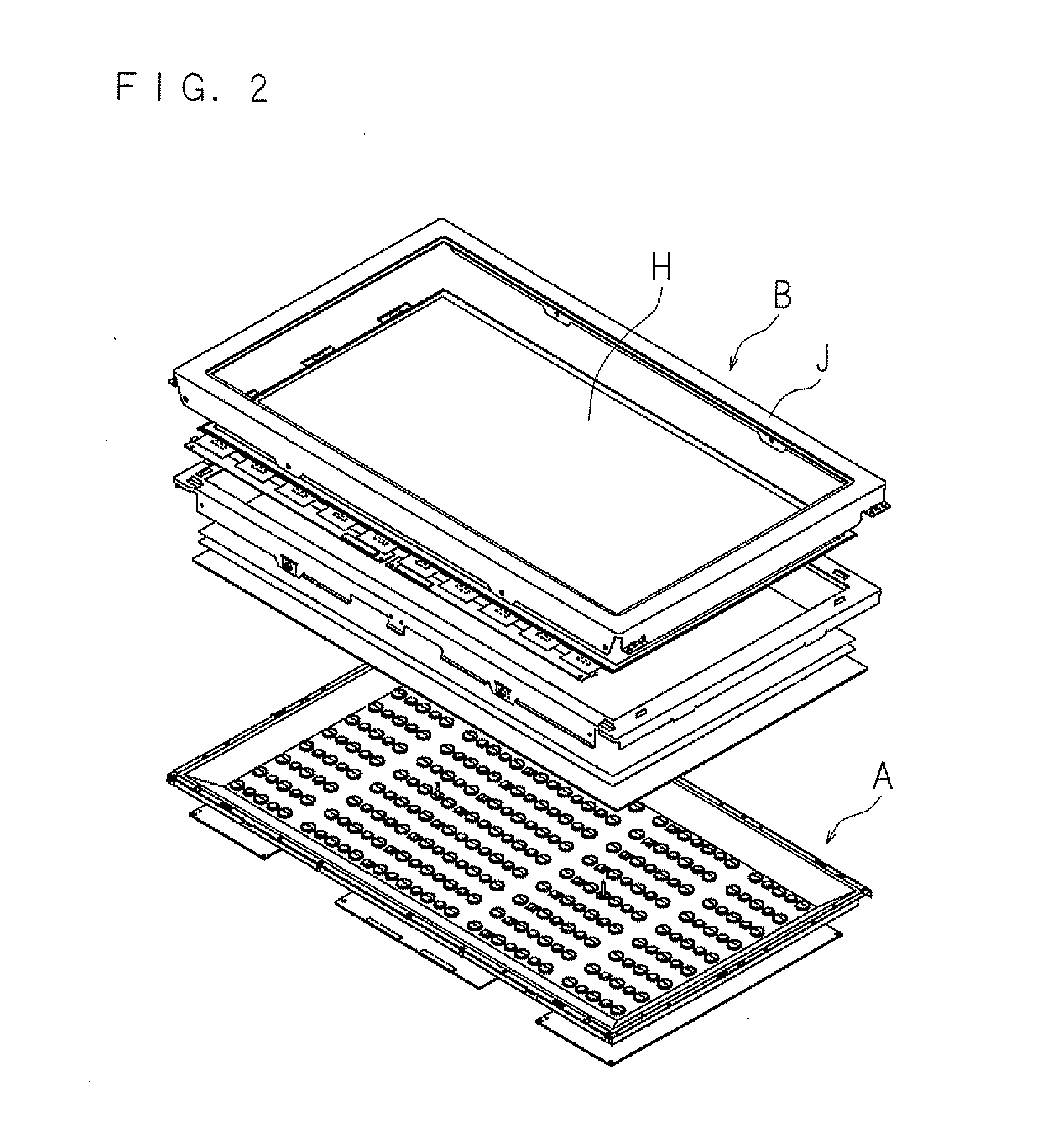
[0132]FIG. 3 is a cross-section view showing a configuration of the image display apparatus including the light source apparatus according to Embodiment 1-1 of the Present Invention. FIG. 4 is a schematical-perspective view showing an exploded part of the light source apparatus, and FIG. 5 is a perspective view showing a configuration of the light source unit of the light source apparatus in the image display apparatus according to Embodiment 1-1 of the present invention.

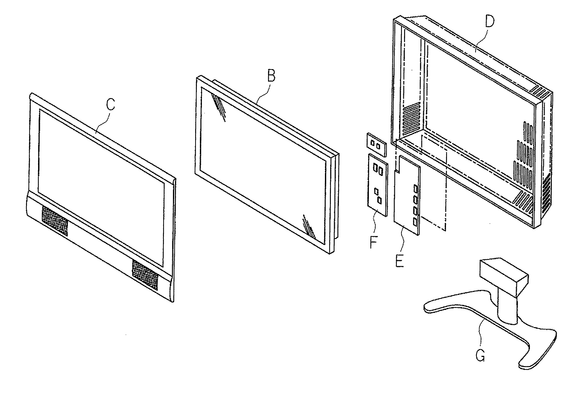
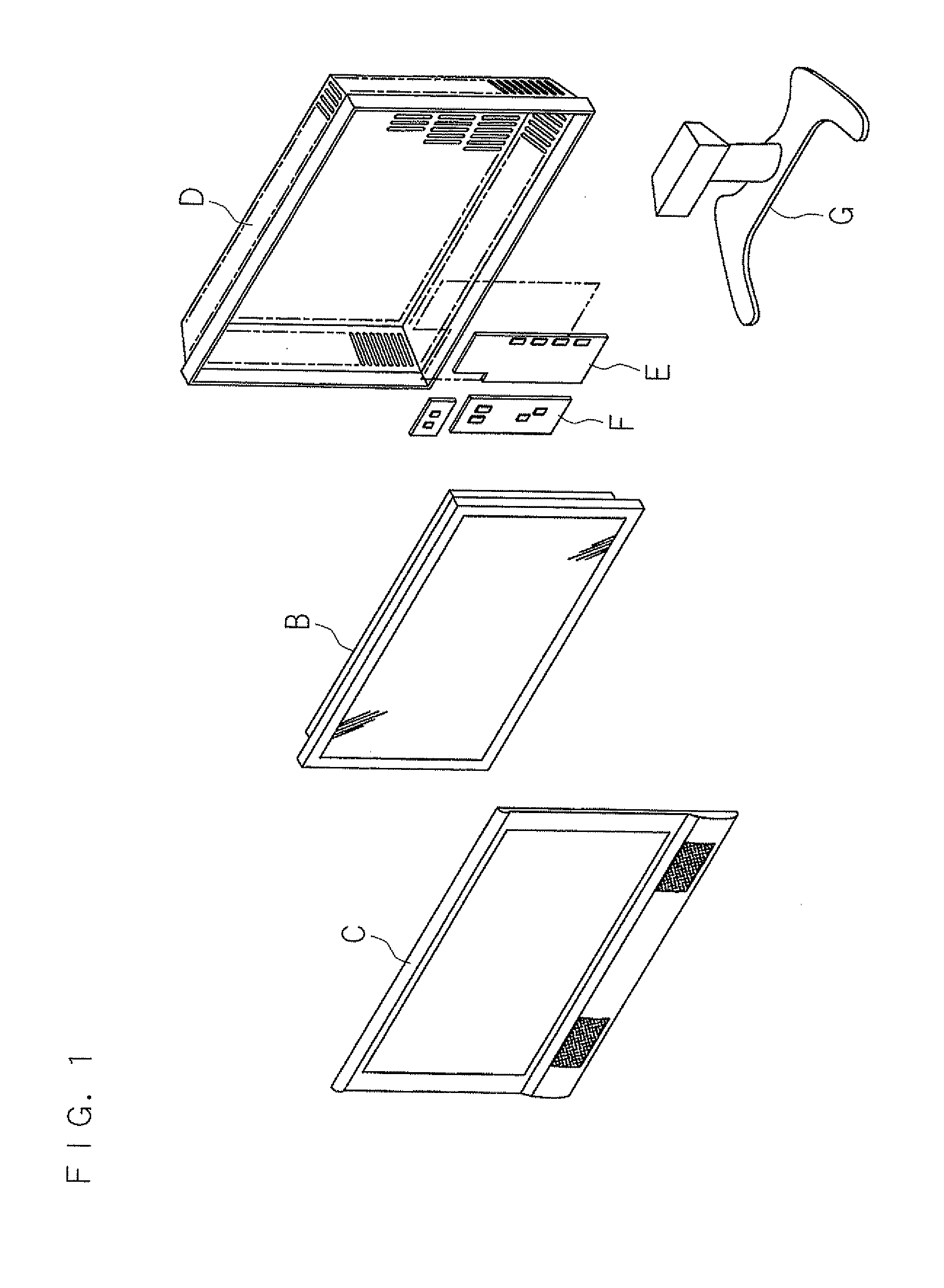
[0133]The image display apparatus 1 according to the present invention includes: a display unit 70 (liquid crystal panel H) that has a display surface at the front side to display an image; a light source apparatus A (back light apparatus) having a light source unit 10 arranged at a side back of the display unit 70; and a cabinet 71 (C, D) covers up the circumference of the display unit 70 and the back side of the light source apparatus A.

[0134]The display unit 70 includes a display panel 72 having the display surfa...

embodiment 1-2

[0162]FIG. 10 is a cross-section view of a main part of an image display apparatus according to Embodiment 1-2 of the present invention, in which the light source unit 10 is supported by the support member 6.

[0163]Plural stoppers 20, 20, . . . 20 making the support member 6 support the light source unit 10 are arranged at plural positions on another surface 2b of the LED board 2. The stopper 20 is made of metal, and is elastically deformable. A plate material is bent in order to obtain the stopper 20. For example, a strip plate material is bent to form symmetrical shape with respect to the center in the longitudinal direction, and the stopper 20 is fixed on another surface 2b to make the short direction become along the longitudinal direction of the LED board 2.

[0164]In short, the stopper 20 consists of a base 20c arranged at the center of the longitudinal direction and a pair of press contact pieces 20d, 20d arranged both edges of the base 20c and extending in the direction leaving...

embodiment 1-3

[0171]FIG. 11 is a cross-section view of a main part of the image display apparatus according to Embodiment 1-3 of the present invention, in which the light source unit 10 is supported by the support member 6.

[0172]Plural stoppers 20, 20, . . . 20 making the support member 6 support the light source unit 10 are arranged at plural positions on another surface 2b of the LED board 2. The stopper 20 is made of metal, and is elastically deformable. A plate material is bent in order to obtain the stopper 20. For example, a strip plate material is bent to form symmetrical shape with respect to the center in the longitudinal direction, and the stopper 20 is fixed on another surface 2b to make the short direction become along the longitudinal direction of the LED board 2.

[0173]In detail, the stopper 20 consists of a flat base 20f arranged at the center of the longitudinal direction, a pair of press contact pieces 20g, 20g arranged both edges of the base 20f and extending in the direction lea...


PUM


Abstract

A light source apparatus, an image display apparatus and a television receiving apparatus are provided, which can electrically connect boards with each other even if the boards are separated from each other by more than or less than a predetermined distance. In a light source unit in which plural LEDs are aligned on one surface of a LED board 2, plural stoppers 20 are arranged at another surface 2b of LED board 2 to stop the stopper 20 at stop slits 63, 63, . . . 63 of a support member 6 which is to hold the light source unit, and to hold the light source unit to be slidable along one surface of the support member 6.

Description

BACKGROUND OF THE INVENTION[0001]1. Field of the Invention[0002]The present invention relates to a light source apparatus, and an image display apparatus and a television receiving apparatus comprising the light source apparatus.[0003]2. Description of Related Art[0004]As for an image display apparatus, for example, a liquid crystal television, there are two types: a behind type in which a fluorescent tube is arranged as a back light on a flat surface behind a liquid crystal display panel displaying an image; and an edge type in which a fluorescent tube is arranged at one side of a backlight plate or fluorescent tubes are arranged at two sides of the backlight plate and light coming to the backlight plate is emitted to a liquid crystal display panel. However, not only the behind type image display apparatus but also the edge type image display apparatus utilizes the fluorescent tube as described above, and has problems that rise in temperature is not uniform and that efficiency for ...

Claims


Application Information

Patent Timeline
Patent Type & Authority Applications(United States)
IPC IPC(8): H04N5/44F21V21/32F21V21/14
CPCH04N5/64F16B5/0642F16B5/0657G02F1/133608F16B5/126F16B19/1081G02F1/133603F16B5/125
Inventor OMIYA, YUKIKAWAMURA, YUUKIWATANABE, TAKEFUMIISHIAI, HIROKAZUTAKEUCHI, HIDETOKATSUKI, MASAYASHINOHARA, KATSUMI
Owner SHARP KK
Why Eureka
Try Eureka