Crest factor reduction for a multicarrier-signal with spectrally shaped single-carrier cancelation pulses

a multi-carrier signal and cancelation pulse technology, applied in the direction of modulated carrier systems, transmission, transmitter/receiver shaping networks, etc., can solve the problems of large linear range of operation of power amplifiers, poor power efficiency, and consumption of power, so as to reduce peak

Active Publication Date: 2012-04-19
KATHREIN SE
View PDF4 Cites 38 Cited by
  • Summary
  • Abstract
  • Description
  • Claims
  • Application Information

AI Technical Summary

Benefits of technology

[0040]applying the combined cancellation pulse to the multi-carrier signal to reduce the peak.

Problems solved by technology

For example, a class A amplifier offers a very low degree of signal distortion, but has poor power efficiency.
A power amplifier with a large linear range of operation typically is more expensive and consumes more power than a power amplifier with a smaller linear range of operation.
A high back-off results in a reduced efficiency for most state-of-the art power amplifier designs.

Method used


Image

  • Crest factor reduction for a multicarrier-signal with spectrally shaped single-carrier cancelation pulses
  • Crest factor reduction for a multicarrier-signal with spectrally shaped single-carrier cancelation pulses
  • Crest factor reduction for a multicarrier-signal with spectrally shaped single-carrier cancelation pulses

Examples


Embodiment Construction

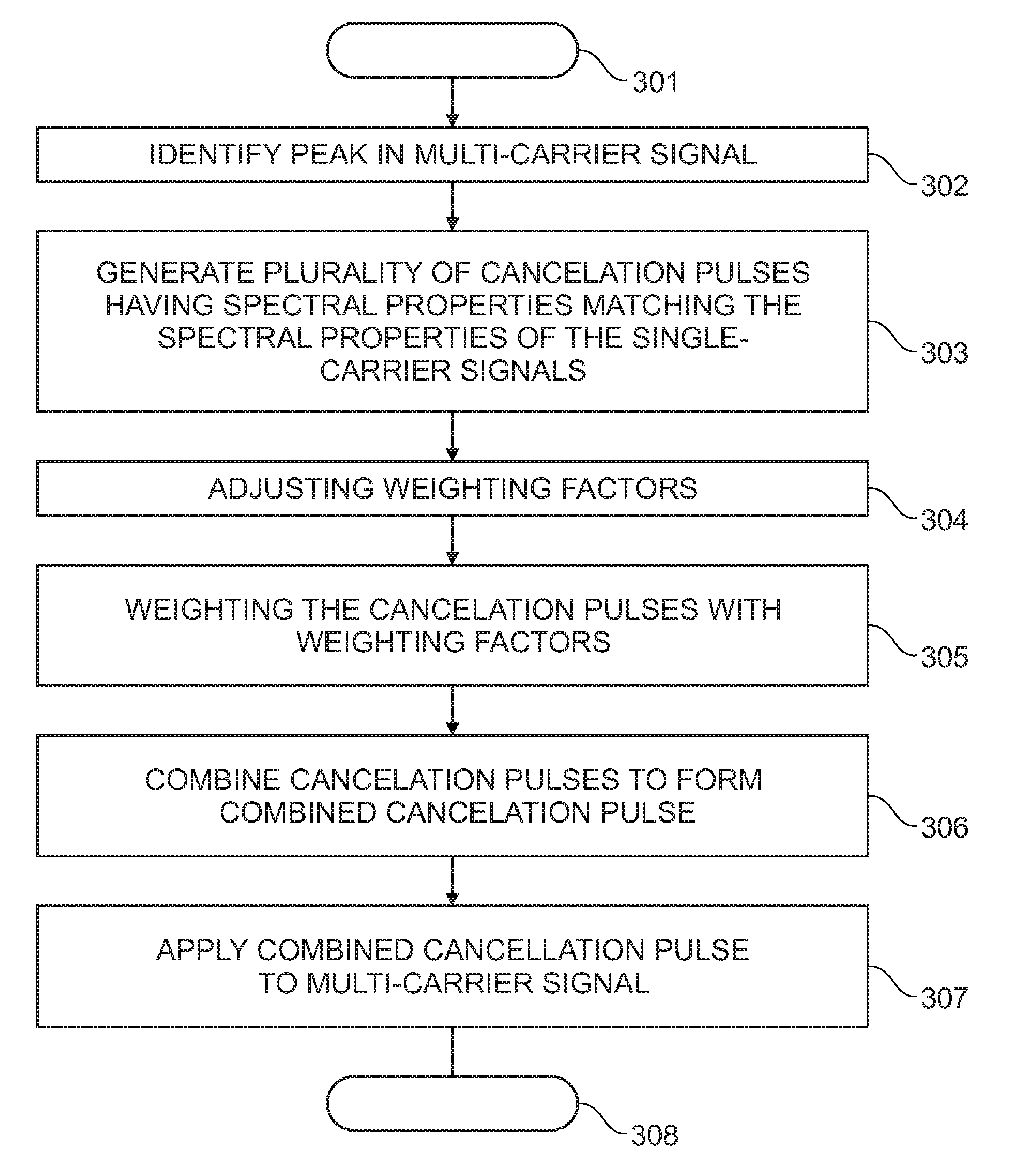
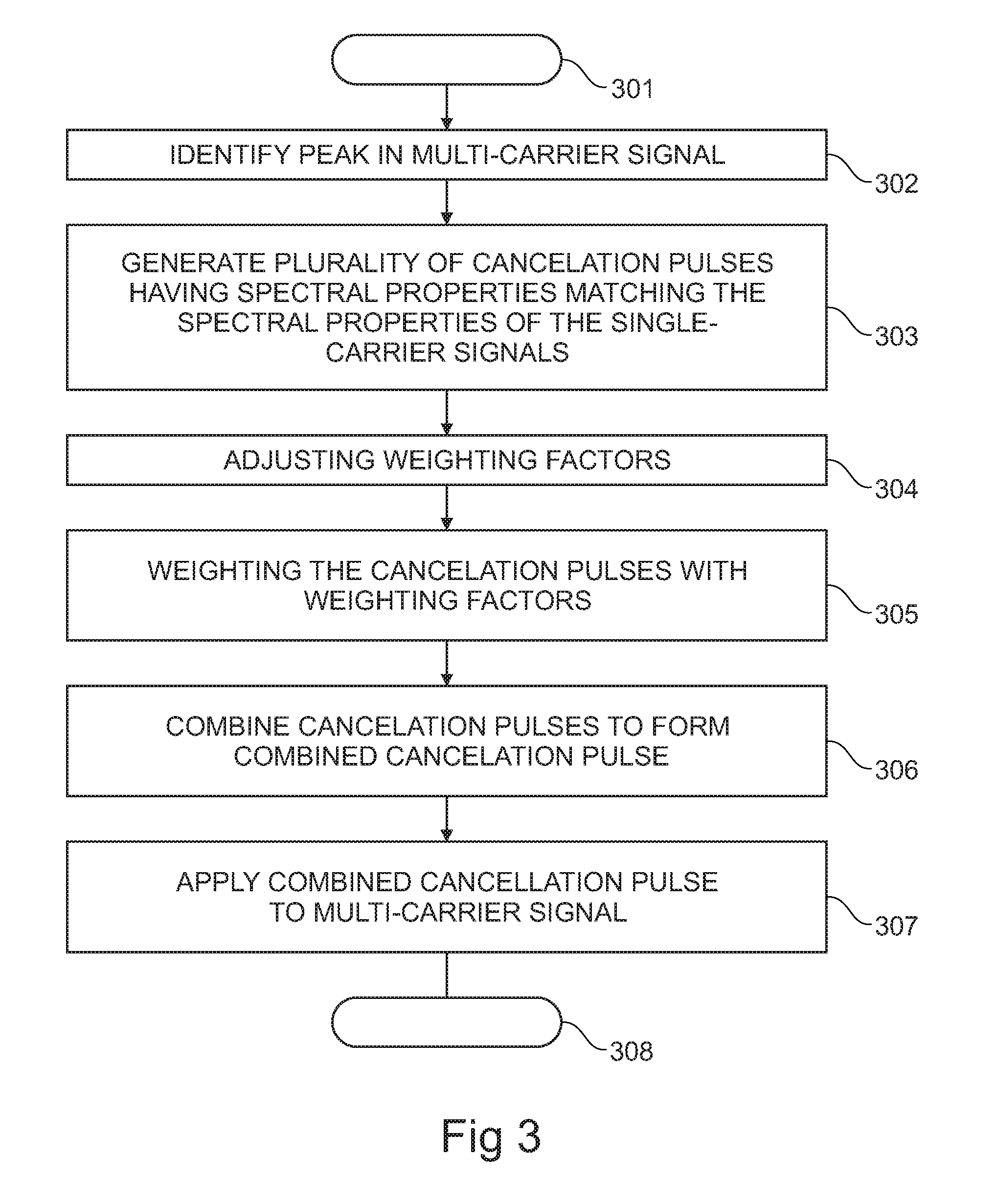
[0050]The invention will now be described on the basis of the drawings. It will be understood that the embodiments and aspects described herein are only examples and do not limit the protective scope of the claims in any way. The invention is defined by the claims and their equivalents. It will also be understood that features of one aspect can be combined with features of a different aspect.

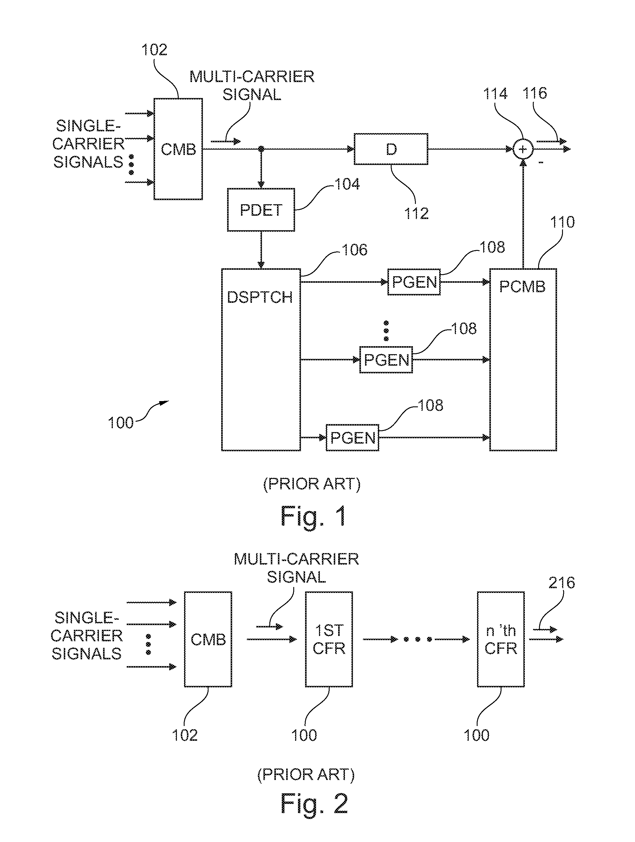
[0051]FIG. 1 shows a schematic block diagram of a crest factor reduction circuit according to the prior art. The crest factor reduction circuit acts on a multi-carrier signal which is generated by combining a plurality of single-carrier signals by means of a combiner 102. Within the crest factor reduction circuit 100, the multi-carrier signal is split and distributed to two paths. The multi-carrier signal per se is sent over a first path which leaves the multi-carrier signal substantially unmodified except for the introduction of a delay by means of a delay element 112 (“D”). The first signal pa...


PUM


Abstract

A method for crest factor reduction of a multi-carrier signal is disclosed. The multi-carrier signal comprises a plurality of single-carrier signals, each single-carrier signal having signal-specific spectral properties. The method comprises identifying a peak in the multi-carrier signal and a time of occurrence of the peak and generating a plurality of cancellation pulses depending on the time of occurrence of the peak. A particular cancellation pulse of the plurality of cancellation pulses is associated with a particular single-carrier signal and cancellation pulse-specific spectral properties of the particular cancellation pulse substantially match the signal-specific spectral properties of the associated particular single-carrier signal. The method further comprises combining the plurality of cancellation pulses to form a combined cancellation pulse and applying the combined cancellation pulse to the multi-carrier signal to reduce the peak. A corresponding circuit and corresponding computer program products useable during manufacture and operation are also disclosed.

Description

CROSS-REFERENCE TO RELATED APPLICATIONS[0001]This application is related to U.S. patent application Ser. No. 12 / 904,538 entitled “Crest factor reduction method and circuit for a multi-carrier signal” filed currently herewith. The entire contents of the forgoing application are incorporated herein by reference.FIELD OF THE INVENTION[0002]The field of the invention relates to a method for crest factor reduction of a multi-carrier signal. The field of the invention also relates to a crest factor reduction circuit for a multi-carrier signal. The field of the invention further relates to a computer program product enabling a foundry to carry out the manufacture of a chip comprising the crest factor reduction circuit, and to a computer program product enabling a processor to execute the method for crest factor reduction of a multi-carrier signal.BACKGROUND OF THE INVENTION[0003]When transmitting radio signals, a transmitter for the radio signal usually comprises a power amplifier. The pow...

Claims


Application Information

Patent Timeline
Patent Type & Authority Applications(United States)
IPC IPC(8): H04L27/28H04B17/00
CPCH04L27/2624
Inventor SCHMIDT, GEORGSCHLEE, JOHANNES
Owner KATHREIN SE
Why Eureka
Try Eureka