Method for the production of a protection device
a protection device and production method technology, applied in the direction of protective equipment, lamination, garments, etc., can solve the problems of high demands on adhesives with which the single tile is assembled in the prior art, high production and handling costs of many single components, and the most vulnerable sites of protection devices, etc., to achieve cost-effective production
- Summary
- Abstract
- Description
- Claims
- Application Information
AI Technical Summary
Benefits of technology
Problems solved by technology
Method used
Image
Examples
example 1
Glass Ceramic Tile Package A
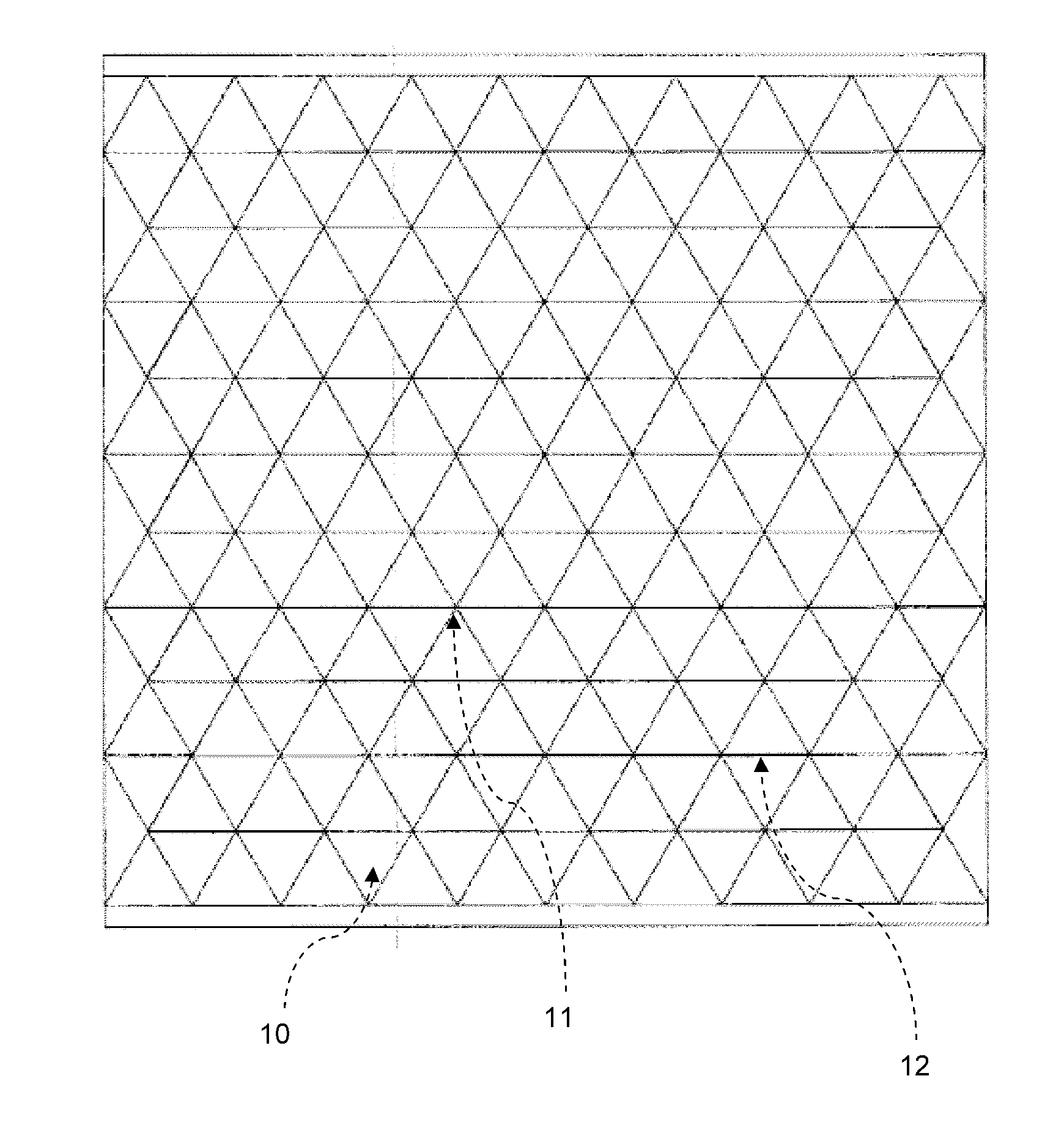
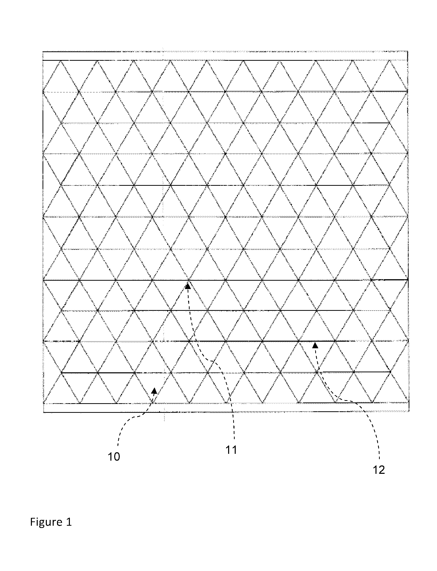
[0056]The upper side of a glass ceramic board, which has a composition in line with DE 10 2008 050 263, a dimension of 500×500×5 mm3 and high quartz mixed crystal as main crystalline phase, is scored with a 135° cutting wheel with the help of Silberschnitt cutting solution (cutting lubricant), wherein a pattern of mainly equilateral triangles having an edge length of 50 mm which corresponds to FIG. 1 is produced.
[0057]A transparent polyurethane foil of the type A4700 (Deerfield Urethane) with a thickness of 0.635 mm is laminated according to the lamination guidelines of Deerfield on the lower side of the scored glass ceramic board, which has burlings. Subsequently, the scoring lines are exposed to tensile stress and the scored glass ceramic board is fractured along the scoring lines, whereby gaps and intersection points are created and a tile package according to the present invention is obtained.
example 2
Glass Ceramic Tile Package B
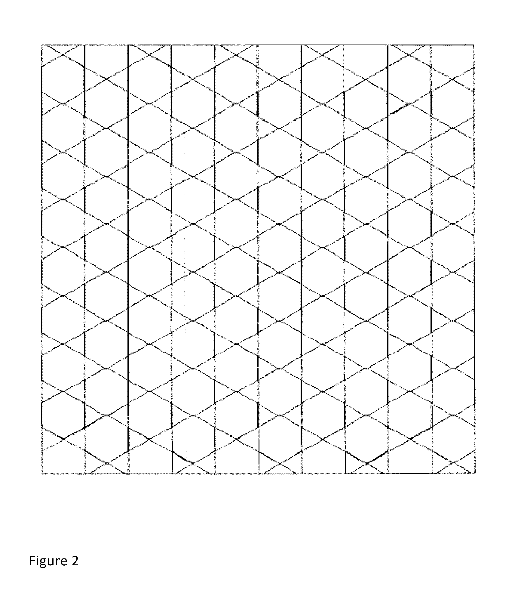
[0058]The upper side of a glass ceramic board, with a composition as described in DE 10 2008 050 263, a dimension of 500×500×8 mm3 and keatite mixed crystal as main crystalline phase is scored with a 140° cutting wheel with the help of “Silberschnitt cutting solution”, wherein a pattern of mainly equilateral triangles and hexagons which corresponds to FIG. 2 is produced. The hexagons have a wrench size of 50 mm and the equilateral triangles have an edge length of 28.87 mm.
[0059]A transparent polyurethane foil of the type A4700 (Deerfield Urethane) with a thickness of 0.635 mm is laminated according to the lamination guidelines of Deerfield on the lower side of the scored glass ceramic board, which has burlings. Subsequently, the scoring lines are exposed to tensile stress and the scored glass ceramic board is fractured along the scoring lines, whereby gaps and intersection points are created and a tile package according to the present invention is obtaine...
example 3
[0060]Two glass ceramic tile packages A are laid on top of each other with an offset of x=25 mm and y=−21.65 mm, as shown in FIG. 3. Below the foil of the glass ceramic tile package, which is not offset, a backing layer of polycarbonate (Makrolon®, Bayer) having a thickness of 5 mm is provided laid on an intermediate layer of transparent polyurethane of the type A4700 (Deerfield Urethane) having a thickness of 1.27 mm. According to the lamination guidelines of Deerfield a glass ceramic-polymer composite is prepared with a final thickness of 17.5 mm. The basis weight is 34.75 kg / m2. This composite withstands a 4 hit bombardment according to the bombardment pattern of ATPD 2352 P (so-called “STANAG-T”) with 5.56×17.8 mm soft-core munition with 315 m / s at a distance of 15 m.
PUM
| Property | Measurement | Unit |
|---|---|---|
| temperature | aaaaa | aaaaa |
| pressure | aaaaa | aaaaa |
| temperature | aaaaa | aaaaa |
Abstract
Description
Claims
Application Information
 - R&D
- Intellectual Property
- Life Sciences
- Materials
- Tech Scout
- Unparalleled Data Quality
- Higher Quality Content
- 60% Fewer Hallucinations
Browse by: Latest US Patents, China's latest patents, Technical Efficacy Thesaurus, Application Domain, Technology Topic, Popular Technical Reports.
© 2025 PatSnap. All rights reserved.Legal|Privacy policy|Modern Slavery Act Transparency Statement|Sitemap|About US| Contact US: help@patsnap.com


