
Method for producing a fibre composite component for air and space technology

a composite component and air and space technology, applied in the direction of sustainable transportation, chemistry apparatus and processes, other domestic articles, etc., can solve the problems of poor adhesive bonding, poor component quality, porous laminates, etc., and achieve the effect of cost effectiv

Active Publication Date: 2012-04-26
AIRBUS OPERATIONS GMBH
View PDF5 Cites 21 Cited by
  • Summary
  • Abstract
  • Description
  • Claims
  • Application Information

AI Technical Summary

Benefits of technology

[0018]Against this background, the object of the present invention is to provide a more cost effective and lighter fibre composite component, in particular for the aerospace industry.

Problems solved by technology

However, supporting cores or mould cores are necessary to produce uncured or cured skin shells reinforced with cured and / or uncured omega stringers.
The supporting core materials investigated hitherto do not always result in a reproducibly good component quality.
So-called “tube bursters” result in porous laminates or in unsatisfactory adhesively bonded joints, and thus entail expensive reworking or result in rejected material.
There is a further problem in the production of skin shells reinforced with omega stringers in that the presently used materials for the supporting or mould core are cost-intensive (in particular hollow profiled parts made of silicone rubber due to a short immobilisation time and possible damage) and they can only be removed with difficulty after the omega stringers have formed (for example due to film inclusions), so that the material remaining in the stringers contributes disadvantageously to the total weight of the aircraft.
Furthermore, pore accumulations and fibre deflections can occur in the skin field which can adversely affect the uniformity, strength and force path in the skin field structure.

Method used


Image

  • Method for producing a fibre composite component for air and space technology
  • Method for producing a fibre composite component for air and space technology
  • Method for producing a fibre composite component for air and space technology

Examples


first embodiment

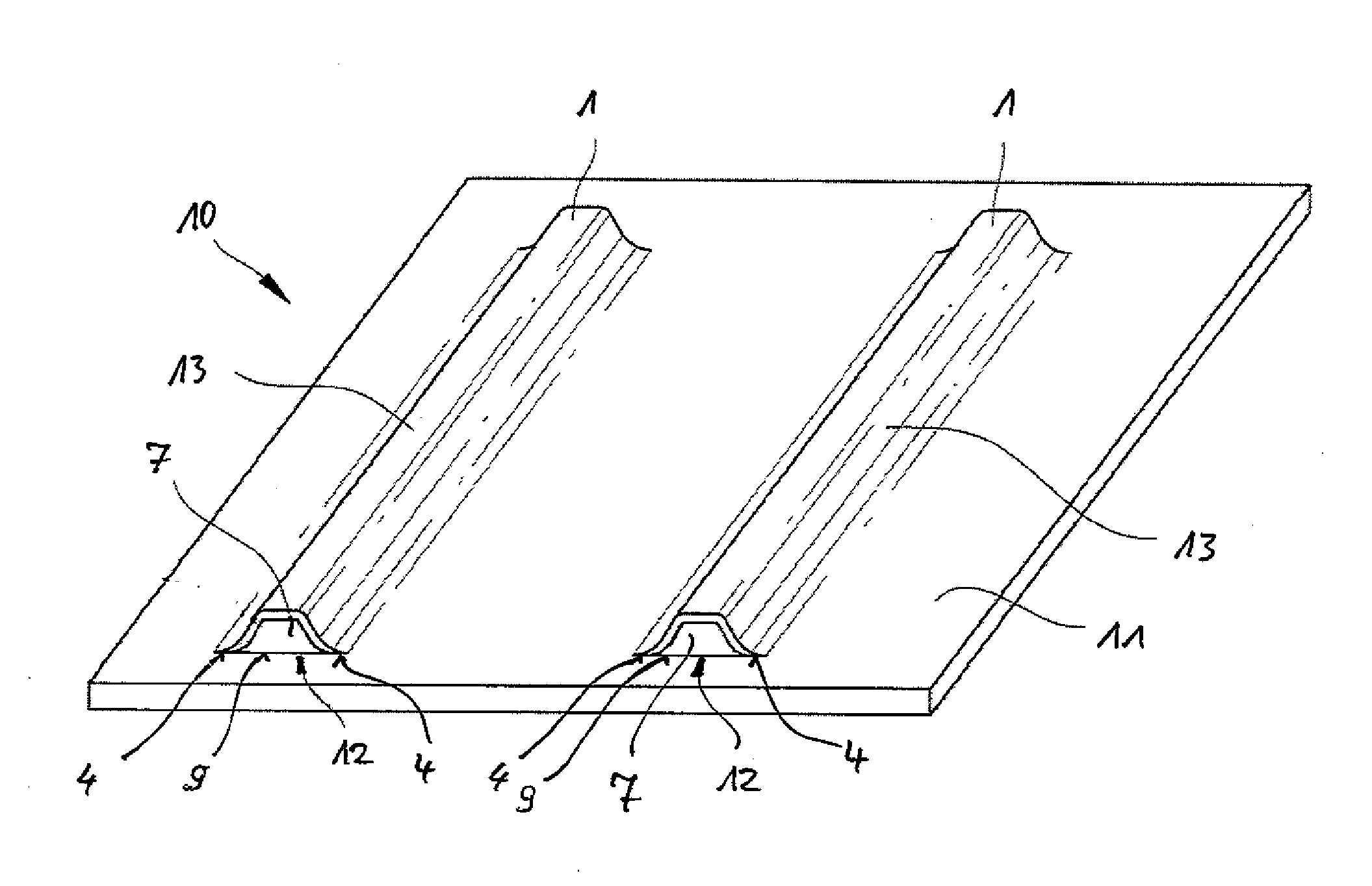
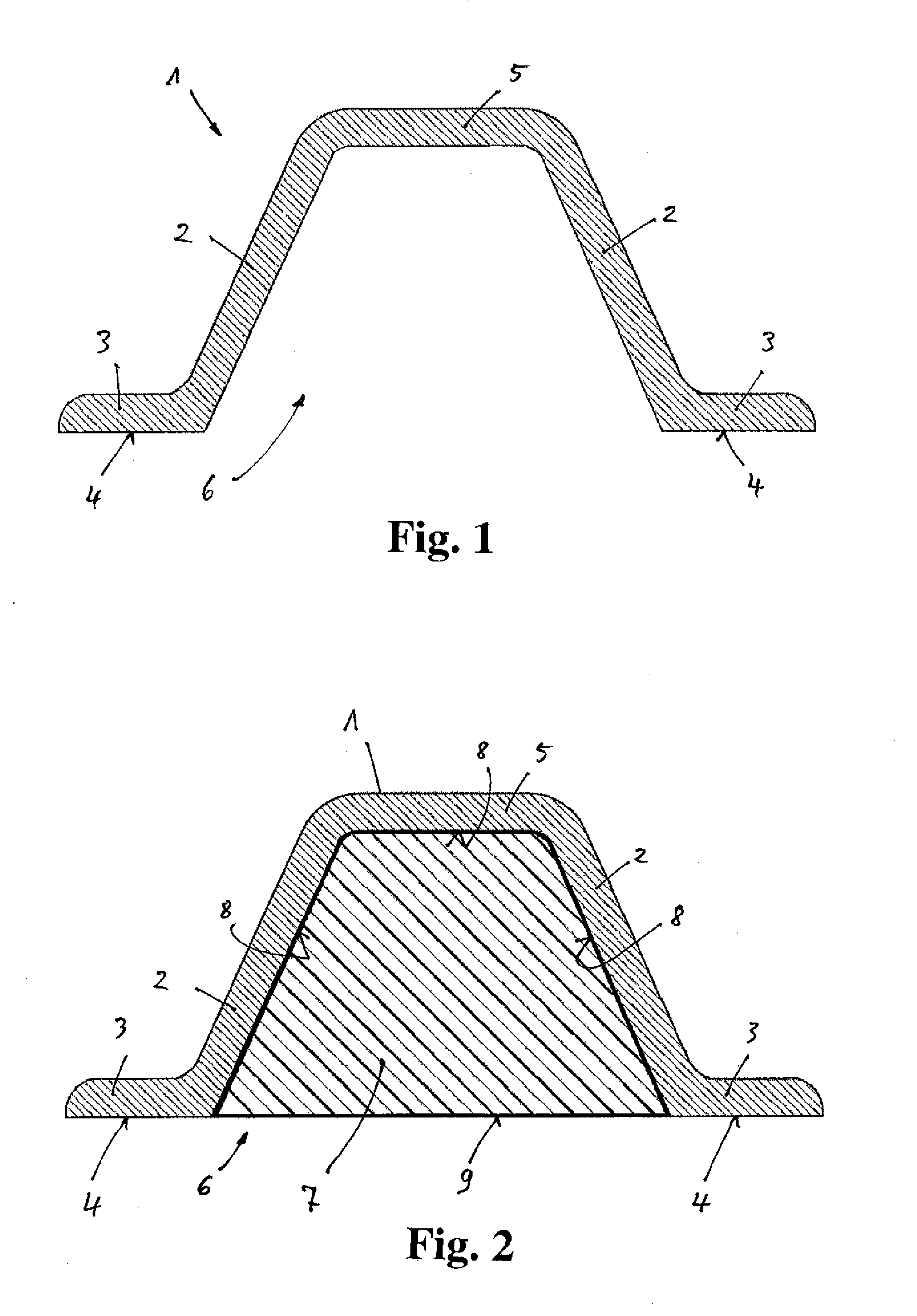
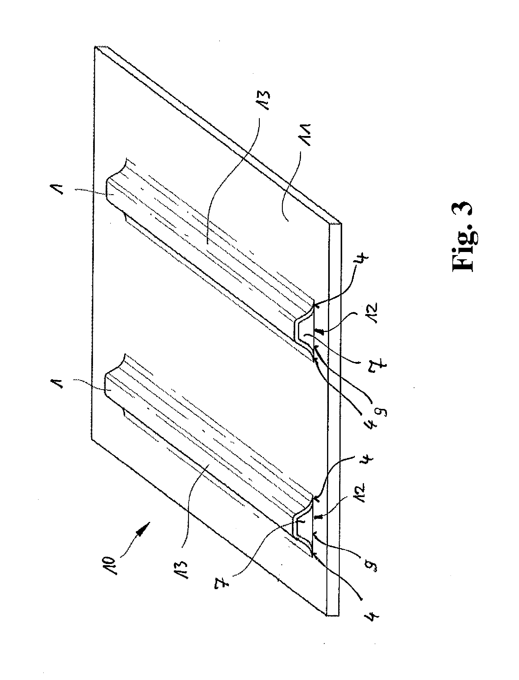
[0069]FIG. 1 is a schematic cross-sectional view of a reinforcing element 1. FIG. 2 shows the view according to FIG. 1 with a cross section of a mould core 7 according to the invention and FIG. 3 is a schematic perspective view of an embodiment of a fibre composite component 10 according to the invention during production according to a first method of the invention.

[0070]In this embodiment, the reinforcing element 1 is a so-called omega stringer with a kind of hat-shaped profile, as shown in FIG. 1, and it stands vertically on the plane of the drawing. A perspective view is provided in FIG. 3, where two reinforcing elements 1, for example, are illustrated which are attached for reinforcement purposes to a base component 11, for example a shell component or a fuselage skin of an aircraft and spacecraft (not shown).

[0071]The reinforcing element 1 (see FIG. 1) has two opposite webs 2 which run obliquely upwards towards one another and are joined together at their upper ends by a horiz...

second embodiment

[0083]FIG. 6 is a schematic cross-sectional view of the mould core 7 according to the invention with the reinforcing element 1 according to FIG. 1. In this embodiment, the mould core 7 is formed with a core inner space 18 which can be filled with a further core during production of the mould core 7. Due to its low weight, this type of mould core 7 is suited, for example to remaining in the reinforcing element 1, a possible core being removed from the core inner space 18.

[0084]In this case, the mould core 7 is used with a reinforcing layer 16 which is, for example, a tear-proof layer of woven fabric. However, it can also be a different reinforcing material, for example a tear-proof separating film. This reinforcing layer 16 can also be used instead of or as the separating layer 15 (see FIGS. 4 and 5). The reinforcing layer 16 is particularly advantageous when the mould core 7 is pulled out on removal from the mould, as it is protected from damage by said layer and its re-usability is...

third embodiment

[0085]FIG. 7 is a schematic, cross-sectional view of the mould core 7 according to the invention with the reinforcing element 1 of FIG. 1, and in this case, the mould core 7 is composed of three core segments 19. Here, the core segments 19 each have triangular cross sections, but are not restricted thereto.

[0086]The core segments 19 are rigidly joined, for example adhesively bonded to one another, the adhesive being suitable for the temperatures and pressures during production of the fibre composite component 10 and resistant to the matrix materials used. This embodiment is suitable for relatively large core cross sections, for example. The core segments 19 can be produced by simple core tools 14.

[0087]FIG. 8 is a schematic cross-sectional view of a fourth embodiment of the mould core 7 according to the invention with the reinforcing element 1 of FIG. 1. In this connection, FIG. 9 is a schematic plan view of a sheet material 20 for producing the mould core 7 of the fourth embodiment...


PUM

PropertyMeasurementUnit
Sizeaaaaaaaaaa

Abstract

A method for producing a fibre composite component, in particular for aerospace, the method comprising the following steps: forming a mould core from a material comprising cork by a moulding tool to establish an outer geometry of said mould core; arranging the so formed mould core adjacent to an at least partly hardened stiffening element on a base element of said composite component to be produced for the shaping of at least one moulded portion of said fibre composite component to be produced; and multistage exposure of at least said moulded portion to heat and / or pressure to produce said fibre composite component; a corresponding mould core and a corresponding fibre composite component.

Description

CROSS-REFERENCE TO RELATED APPLICATIONS[0001]This application is a continuation of and claims priority to PCT / EP2010 / 055451 filed Apr. 23, 2010 which claims the benefit of and priority to U.S. Provisional Application No. 61 / 214,877, filed Apr. 28, 2009 and German Patent Application No. 10 2009 002 697.5 filed Apr. 28, 2009, the entire disclosures of which are herein incorporated by reference.FIELD OF THE INVENTION[0002]The present invention relates to a method for producing a fibre composite component, in particular for the aviation and aerospace industry, to a mould core for producing a fibre composite component of this type and to a fibre composite component which has at least one reinforcing element which is produced by a mould core of this type and / or by a method of this type.[0003]Although the present invention and the problem on which it is based can be applied to any fibre composite components, they will be described in more detail in the following with reference to planar ca...

Claims


Application Information

Patent Timeline
IPC IPC(8): B32B37/02B29C33/76B32B37/10B32B37/14B32B37/06
CPCB29C33/76B29C70/086B29C70/30Y10T156/1028B29L2031/3076Y02T50/433Y02T50/43B29K2711/02Y02T50/40
Inventor NITSCH, CHRISTIAN
Owner AIRBUS OPERATIONS GMBH
Learn More