
Dual delivery chamber design

a delivery chamber and dual-channel technology, applied in the direction of coatings, metallic material coating processes, chemical vapor deposition coatings, etc., can solve the problems of recombined neutral radicals, and achieve the effect of preventing any thermal damage to the substrate and keeping the substrate cool

Inactive Publication Date: 2012-04-26
APPLIED MATERIALS INC
View PDF4 Cites 165 Cited by
  • Summary
  • Abstract
  • Description
  • Claims
  • Application Information

AI Technical Summary

Benefits of technology

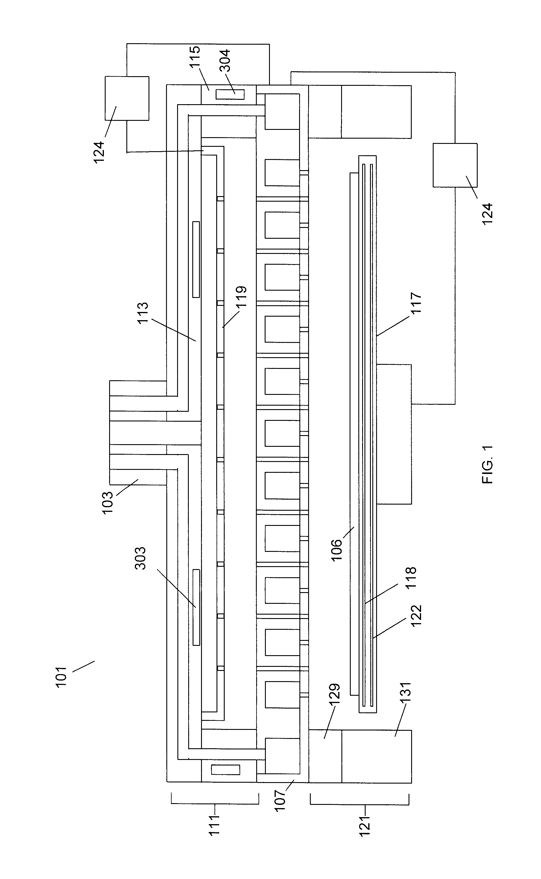
[0011]In other embodiments, the antechamber can include a plasma generator. Various types of plasma generators can be used including: capacitively coupled, inductively coupled, optical or any other suitable types of plasma generator. Because the plasma generator is directly over the showerhead and the processing chamber containing the substrate and pedestal are directly under the showerhead, the loss of charged species is minimized.
[0014]The configuration of the plasma generator directly above the showerhead improves the percentage of reactive gases that enter the processing chamber which can be neutral radicals or charged particles. Thus, a much higher percentage of neutral radicals or charged particles enter the processing chamber in comparison to a remote plasma source. Since the efficiency of the system is greatly enhanced, a much lower number of neutral radicals or charged particles need to be produced to perform the required wafer processing.
[0018]The inventive processing system can be used for “cold” processing of substrates where the substrate is kept less than 100° C. The cooler processing temperature prevents any thermal damage of the substrate. The processor can keep the substrate cool by keeping the RF energy away from the substrate. The RF energy is isolated from the substrate by the faceplate. A temperature controlled pedestal is disclosed in copending U.S. patent application Ser. No. 12 / 641,819, Multifunctional Heater / Chiller Pedestal For Wide Range Wafer Temperature Control filed Dec. 18, 2009, which is hereby incorporated by reference.

Problems solved by technology

A problem with a remote plasma source is that a large percentage, possibly 80%, of the neutral radicals are recombined before reaching the wafer processing chamber.
Again, the problem with a remote plasma source is that a large percentage of the charged species produced by the plasma are recombined before reaching the wafer processing chamber.

Method used


Image

  • Dual delivery chamber design
  • Dual delivery chamber design
  • Dual delivery chamber design

Examples


Embodiment Construction

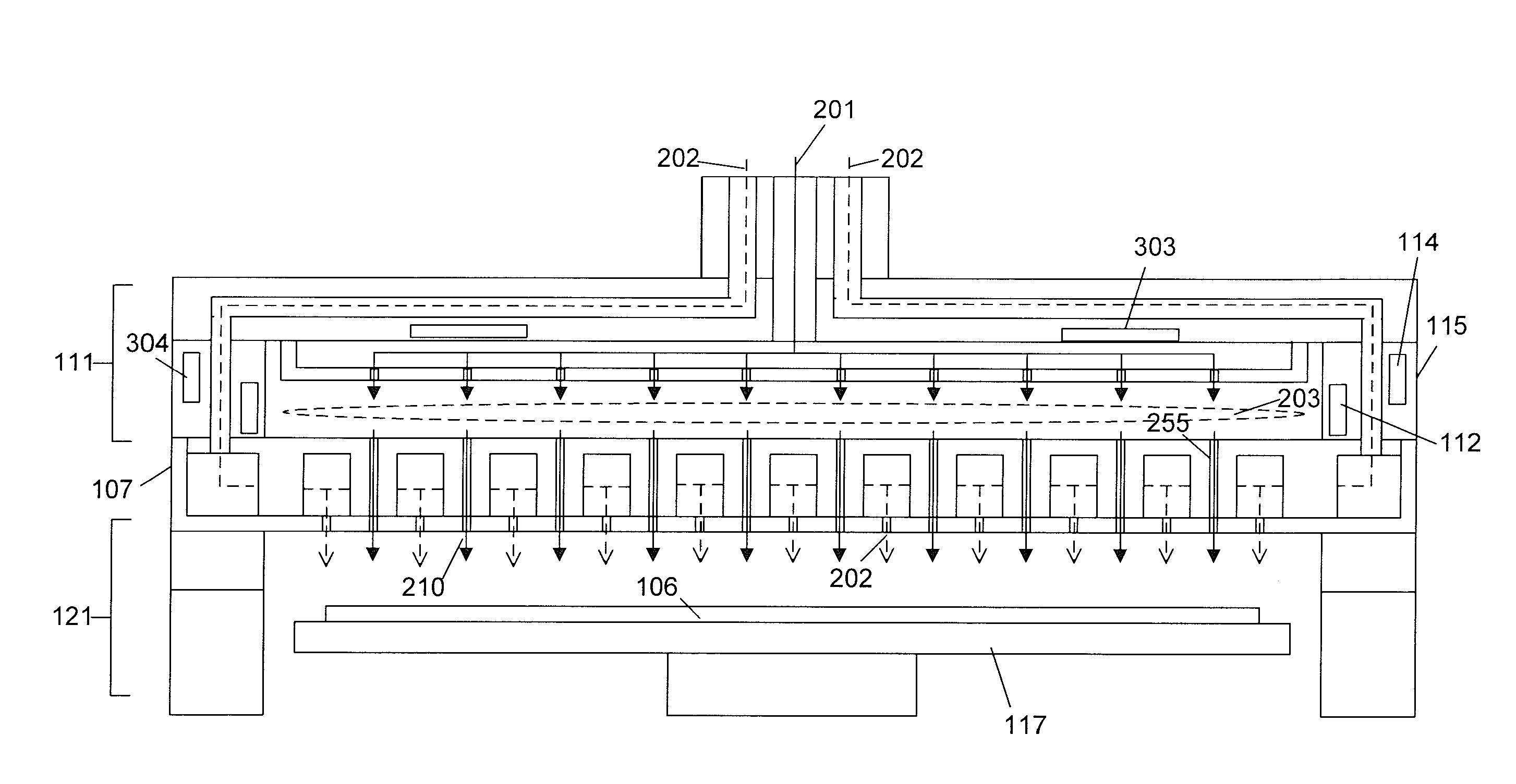
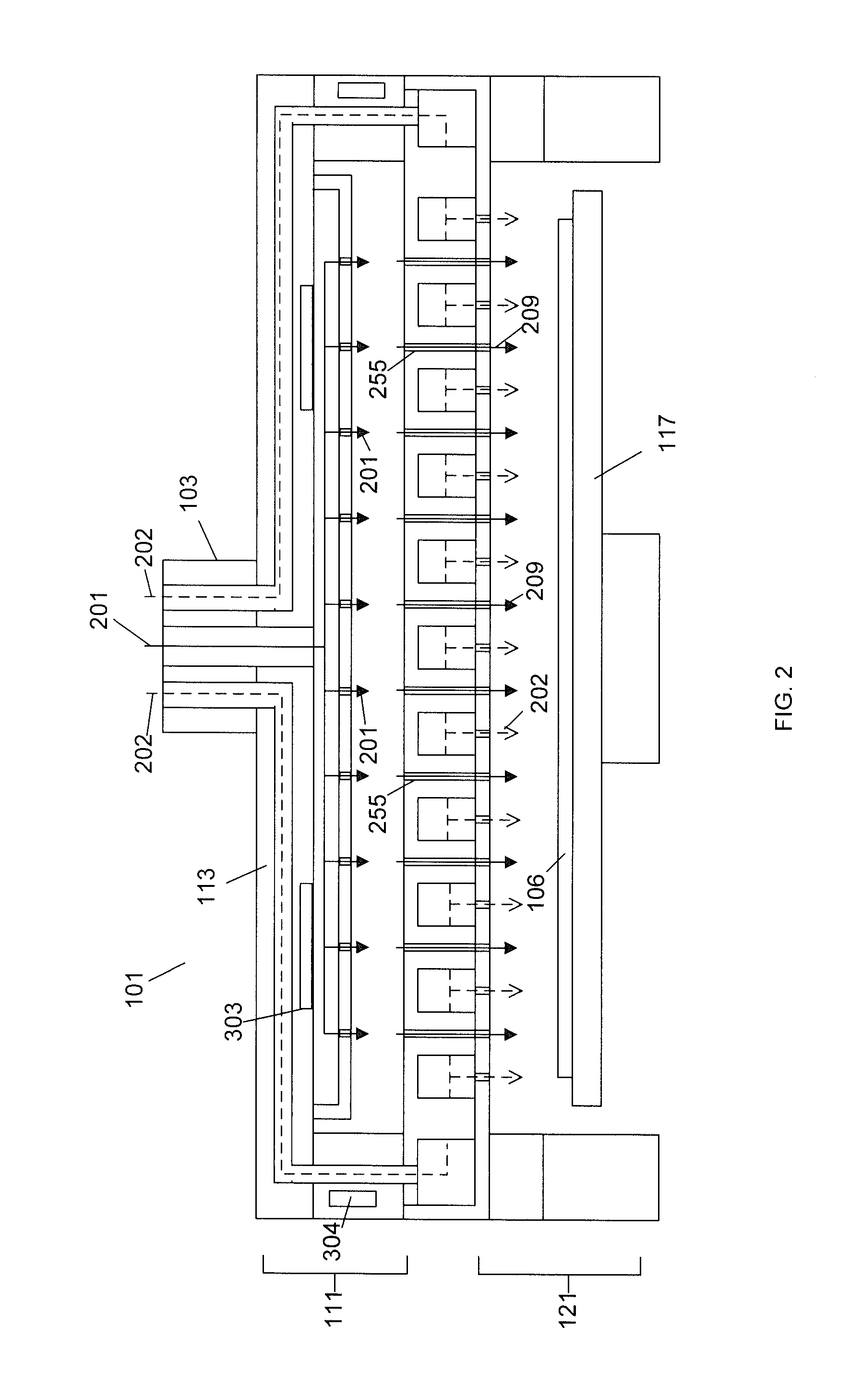
[0033]The present disclosure is directed towards a modular precursor gas processing system that is used for chemical vapor deposition (CVD). With reference to FIG. 1, a cross sectional view of an embodiment of the CVD processing system 101 is illustrated. The plasma processing system 101 includes an antechamber 111, a processing chamber 121 and the showerhead 107 that separates the antechamber 111 from the processing chamber 121. The system 101 also includes a manifold 103, a gas box 113, a spacer ring 115, a blocker plate 119, a pedestal 117, an isolator 129 and a body 131.

[0034]A substrate 106, such as a semiconductor wafer, is maintained proximate the processing chamber 121 upon the pedestal 117. The pedestal 117 may be able to move vertically within the processing chamber 121 to lower the pedestal 117 to a position that allows a substrate 106 to be inserted or removed from the processing chamber 101 through a slit valve (not shown) while in the lowered position. When the pedesta...


PUM

PropertyMeasurementUnit
temperatureaaaaaaaaaa
pressureaaaaaaaaaa
temperatureaaaaaaaaaa

Abstract

A substrate processing system includes a thermal processor or a plasma generator adjacent to a processing chamber. A first processing gas enters the thermal processor or plasma generator. The first processing gas then flows directly through a showerhead into the processing chamber. A second processing gas flows through a second flow path through the showerhead. The first and second processing gases are mixed below the showerhead and a layer of material is deposited on a substrate under the showerhead.

Description

BACKGROUND[0001]1. Field of Invention[0002]The present invention relates to semiconductor wafer processing systems and, more particularly, to a gas distribution showerhead for supplying at least two process gases to a reaction chamber of a semiconductor wafer processing system.[0003]2. Description of the Related Art[0004]Semiconductor wafer processing systems generally contain a process chamber having a pedestal for supporting a semiconductor wafer within the chamber proximate a processing region. The chamber forms a vacuum enclosure defining, in part, the process region. A gas distribution assembly or showerhead provides one or more process gases to the process region. The gases can be heated and / or supplied with RF energy which causes the molecules to disassociate. The process gases can then be mixed and used to perform certain processes on the wafer. These processes may include chemical vapor deposition (CVD) to deposit a film upon the wafer or etching to remove material from the...

Claims


Application Information

Patent Timeline
Patent Type & Authority Applications(United States)
IPC IPC(8): H01L21/465H01L21/46
CPCC23C16/45565C23C16/4557C23C16/45574H01L21/02274C23C16/5096H01L21/02164C23C16/463
Inventor IYENGAR, PRAHALLADBALUJA, SANJEEVDUBOIS, DALE R.ROCHA-ALVEREZ, JUAN CARLOSNOWAK, THOMASHENDRICKSON, SCOTT A.LEE, YONG-WONSHEK, MEI-YEEXIA, LI-QUNWITTY, DEREK R.
Owner APPLIED MATERIALS INC
Learn More