Selective hydrate production with co2 and controlled depressurization

Inactive Publication Date: 2012-04-26
CONOCOPHILLIPS CO
View PDF2 Cites 7 Cited by
  • Summary
  • Abstract
  • Description
  • Claims
  • Application Information

AI Technical Summary

Benefits of technology

[0009]In an embodiment, a method for the producing hydrocarbons from a subterranean formation containing gas hydrates, the method includes: (a) drilling a well into a subterranean formation; (b) introducing a releasing agent into the well in a controlled manner to partially depressurize the well, wherein the releasing agent is more thermodynamically stable than the gas hydrates present in the formation; (c) causing the releasing agent to contact the gas hydrates, thereby releasing the hydrocarbons in the well without melting the gas hydrate; (d) selectively substituting the releasing agent for the hydrocarbons to thereby release the hydrocarbons from solid-state hydrate structure s without melting the gas hydrates, thereby providing substituted hydrates comprising the releasing agent bound with the solid-state hydrate structures that form hydrates, thereby releasing the hydrocarbons into the well without melting the gas hydrates; and (e) reducing the pressure in the well to selectively dissociate the hydrates with a desired methane content.

Problems solved by technology

It is not uncommon for solid hydrates to cause plugging and / or blockage of pipelines or transfer lines or other conduits, valves and / or safety devices and / or other equipment, resulting in shutdown, loss of production, and risk of explosion or unintended release of hydrocarbons into the environment either on-land or off-shore.
The smaller or lower-boiling hydrocarbon molecules, particularly C1 (methane) to C4 hydrocarbons and their mixtures, are often the most problematic in the oil and gas industry because they form in hydrate or clathrate crystals under a wide range of production conditions.
However, there are two major problems with these known methods.
First, these known methods can require a large amount of energy to be added to the system, especially in heating methods, resulting in a high cost of extraction.
Second, they destabilize hydrate formations because both depressurization and heating cause the hydrate to dissociate.
This can lead to the destabilization and / or collapse of sediments that contain hydrates and other nearby subterranean reservoirs.
Because gas hydrates are often located near oil and natural gas deposits, such instability during extraction can result in problems with the extraction of oil and natural gas.
However, the hydrate production from depressurization suffers from several limitations including, but not limited to: significant production of water, endothermic cooling, and loss of geomechanical stability as hydrates dissociate.
Furthermore, depressurizing inside the well will not necessarily lead to depressurization of the entire methane hydrate-bearing layer.

Method used


Image

  • Selective hydrate production with co2 and controlled depressurization
  • Selective hydrate production with co2 and controlled depressurization

Examples


Embodiment Construction

[0013]Reference will now be made in detail to embodiments of the present invention, one or more examples of which are illustrated in the accompanying drawings. Each example is provided by way of explanation of the invention, not as a limitation of the invention. It will be apparent to those skilled in the art that various modifications and variations can be made in the present invention without departing from the scope or spirit of the invention. For instance, features illustrated or described as part of one embodiment can be used on another embodiment to yield a still further embodiment. Thus, it is intended that the present invention cover such modifications and variations that come within the scope of the appended claims and their equivalents.

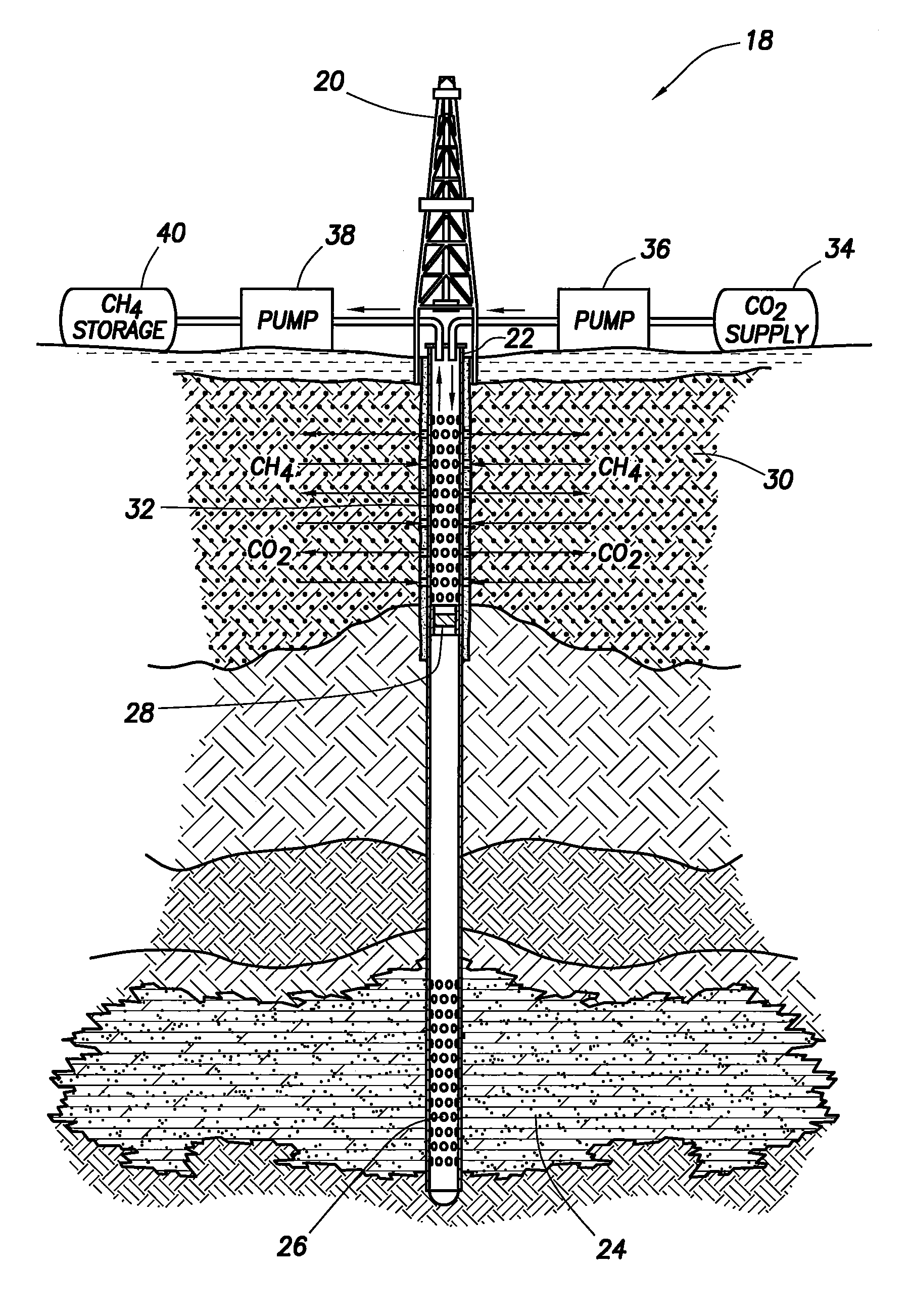
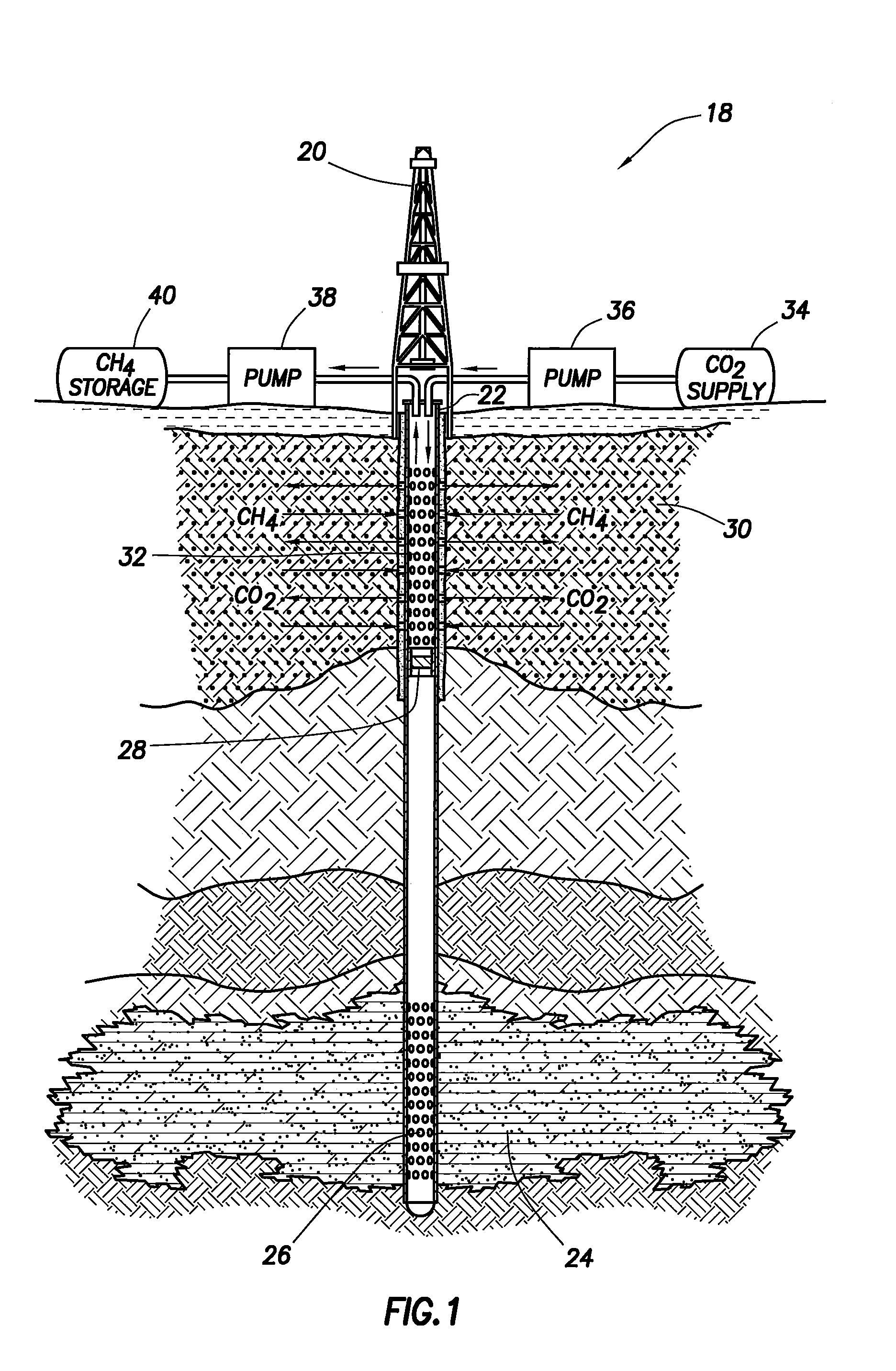
[0014]Methane hydrate conversion to carbon dioxide hydrate requires an understanding of hydrodynamics of carbon dioxide injection and transport to the methane hydrate accumulation; along with thermodynamics of formation and dissociation of t...


PUM


Abstract

The present invention relates to an improved method for recovering hydrocarbons trapped in hydrate formations.

Description

CROSS-REFERENCE TO RELATED APPLICATIONS[0001]This application claims priority benefit under 35 U.S.C. Section 119(e) to U.S. Provisional Patent Ser. No. 61 / 406,261 filed on Oct. 25, 2010 the entire disclosure of which is incorporated herein by reference.FIELD OF THE INVENTION[0002]The present invention relates to an improved method for recovering hydrocarbons trapped in hydrate formations.BACKGROUND OF THE INVENTION[0003]A number of hydrocarbons, especially lower boiling-point light hydrocarbons, in formation fluids or natural gas, are known to form hydrates in conjunction with the water present under a variety of conditions—particularly at a combination of lower temperature and higher pressure. The hydrates are solid crystalline compounds which co-exist with the surrounding porous media or natural gas fluids. Any solids in formation or natural gas fluids are at the least a nuisance for production, handling, and transport of these fluids. It is not uncommon for solid hydrates to cau...

Claims


Application Information

Patent Timeline
IPC IPC(8): E21B43/00
CPCE21B41/0064Y02C10/14E21B2043/0115E21B41/0099Y02C20/40
Inventor HESTER, KEITH C.HOWARD, JAMES J.
Owner CONOCOPHILLIPS CO
Why Eureka
Try Eureka