
Method to control an arc welding system to reduce spatter

a technology of arc welding and control method, which is applied in the direction of arc welding apparatus, welding apparatus, manufacturing tools, etc., can solve the problem of lower welding current than it is otherwise, and achieve the effect of reducing spatter, reducing spatter, and reducing welding output curren

Active Publication Date: 2012-04-26
LINCOLN GLOBAL INC
View PDF9 Cites 68 Cited by
  • Summary
  • Abstract
  • Description
  • Claims
  • Application Information

AI Technical Summary

Benefits of technology

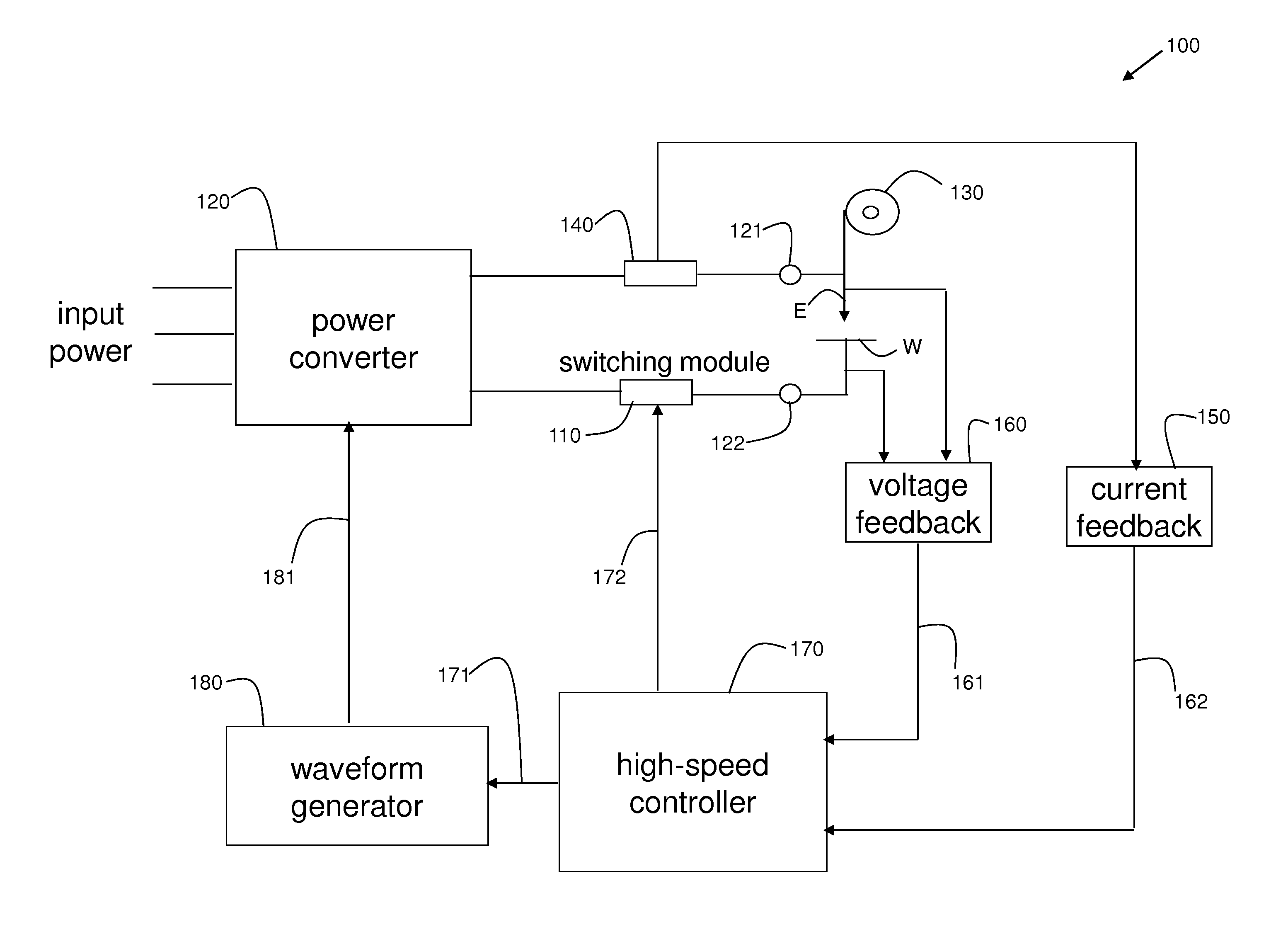
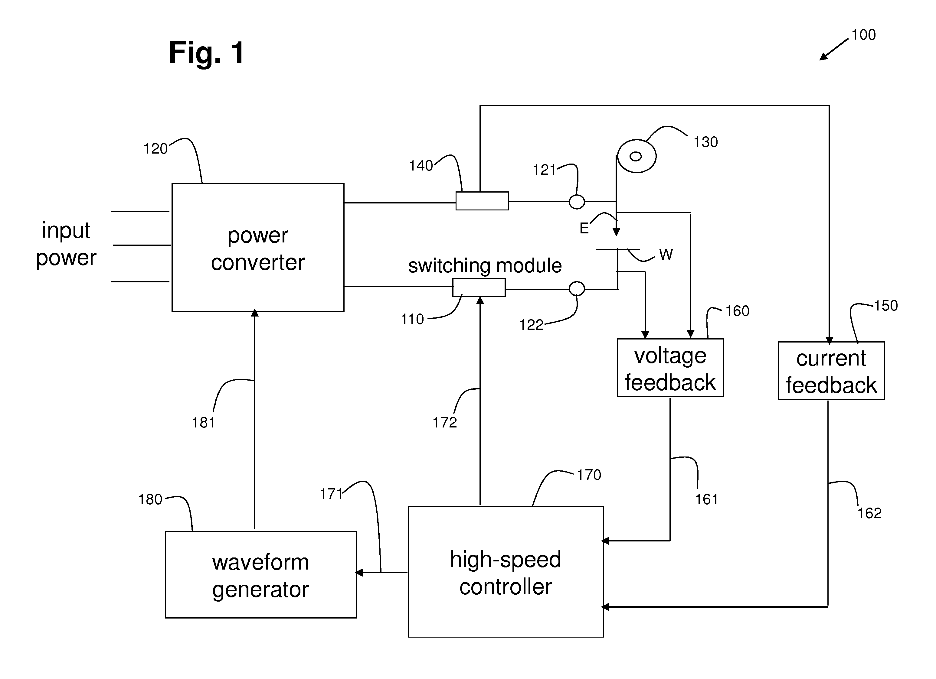
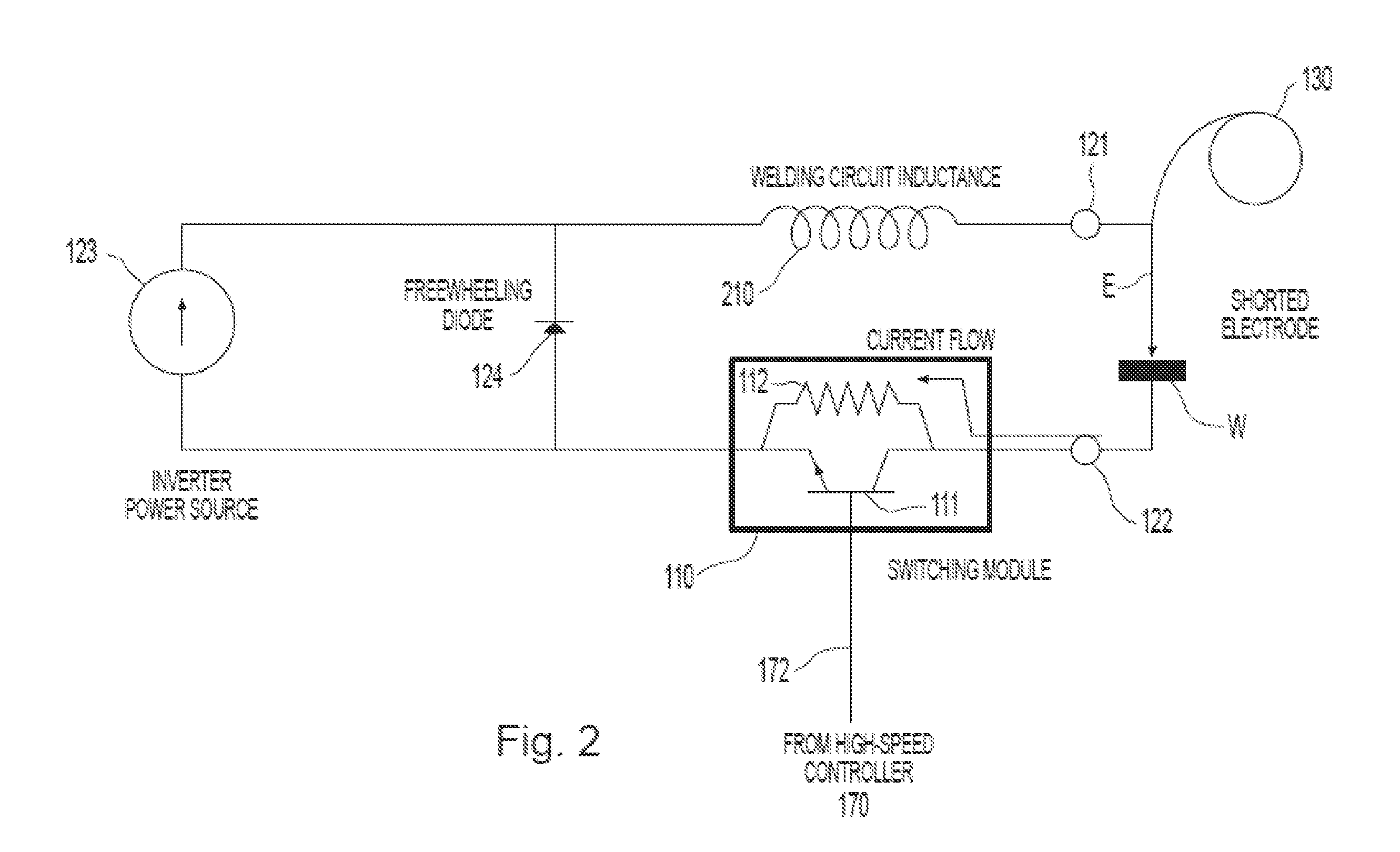
[0007]Embodiments of the present invention comprise an electric arc welding system and methods for reducing spatter during a pulsed electric arc welding process. Spatter is reduced during a welding operation by reducing the welding output current during a time when a short occurs between the welding electrode and the workpiece. In one embodiment, a switching module, including an electrical switch and a resistive path, is incorporated into the return welding current path of a power source of the electric arc welding system. During non-shorting conditions of the pulse welding operation, the electrical switch is closed or on, allowing welding current to freely return to the power source by experiencing minimal resistance through the switch. However, when a short is anticipated or occurs during the welding process, the electrical switch is opened or turned off, forcing the welding current to have to go through the resistive path of the switching module, causing the level of the welding current to be lower than it otherwise would be. The lower current generated during the short interval results in less spatter being created when the short is cleared. The time of occurrence of a short during the pulse periods may be tracked and a blanking interval, overlapping the interval of time corresponding to an anticipated short, may be applied such that the switch is open during the blanking interval.
[0004]Certain embodiments relate to pulsed electric arc welding equipment and processes. More particularly, certain embodiments relate to anticipating or reacting to short circuits formed between a welding electrode and a workpiece during a pulsed electric arc welding process by reducing the output current during the time of the short to reduce spatter.
[0007]Embodiments of the present invention comprise an electric arc welding system and methods for reducing spatter during a pulsed electric arc welding process. Spatter is reduced during a welding operation by reducing the welding output current during a time when a short occurs between the welding electrode and the workpiece. In one embodiment, a switching module, including an electrical switch and a resistive path, is incorporated into the return welding current path of a power source of the electric arc welding system. During non-shorting conditions of the pulse welding operation, the electrical switch is closed or on, allowing welding current to freely return to the power source by experiencing minimal resistance through the switch. However, when a short is anticipated or occurs during the welding process, the electrical switch is opened or turned off, forcing the welding current to have to go through the resistive path of the switching module, causing the level of the welding current to be lower than it otherwise would be. The lower current generated during the short interval results in less spatter being created when the short is cleared. The time of occurrence of a short during the pulse periods may be tracked and a blanking interval, overlapping the interval of time corresponding to an anticipated short, may be applied such that the switch is open during the blanking interval.
[0007]Embodiments of the present invention comprise an electric arc welding system and methods for reducing spatter during a pulsed electric arc welding process. Spatter is reduced during a welding operation by reducing the welding output current during a time when a short occurs between the welding electrode and the workpiece. In one embodiment, a switching module, including an electrical switch and a resistive path, is incorporated into the return welding current path of a power source of the electric arc welding system. During non-shorting conditions of the pulse welding operation, the electrical switch is closed or on, allowing welding current to freely return to the power source by experiencing minimal resistance through the switch. However, when a short is anticipated or occurs during the welding process, the electrical switch is opened or turned off, forcing the welding current to have to go through the resistive path of the switching module, causing the level of the welding current to be lower than it otherwise would be. The lower current generated during the short interval results in less spatter being created when the short is cleared. The time of occurrence of a short during the pulse periods may be tracked and a blanking interval, overlapping the interval of time corresponding to an anticipated short, may be applied such that the switch is open during the blanking interval.

Problems solved by technology

However, when a short is anticipated or occurs during the welding process, the electrical switch is opened or turned off, forcing the welding current to have to go through the resistive path of the switching module, causing the level of the welding current to be lower than it otherwise would be.

Method used


Image

  • Method to control an arc welding system to reduce spatter
  • Method to control an arc welding system to reduce spatter
  • Method to control an arc welding system to reduce spatter

Examples


Embodiment Construction

[0018]During an arc-welding process, when the distance between the tip of the electrode and the workpiece is relatively small, molten metal may be transferred via a contact transfer process (e.g., a surface-tension-transfer or STT process) or a free-flight transfer process (e.g., a pulsed welding process) with a tethered connection. In a contact transfer process, a molten metal ball on the tip of the welding electrode makes contact with the workpiece (i.e., shorts) and starts to “wet into” the molten puddle on the workpiece before the molten metal ball begins to substantially separate from the tip of the electrode.

[0019]In a free-flight transfer process, the molten metal ball breaks free of the tip of the electrode and “flies” across the arc toward the workpiece. However, when the distance between the tip of the electrode and the workpiece is relatively short, the molten metal ball flying across the arc can make contact with the workpiece (i.e., short) while a thin tether of molten ...


PUM

PropertyMeasurementUnit
resistanceaaaaaaaaaa
electricalaaaaaaaaaa
currentaaaaaaaaaa

Abstract

An electric arc welder and a method for performing a pulse welding process producing reduced spatter. The welder produces a current between an advancing electrode and a workpiece. The welder includes a short-detecting capability for detecting a short condition upon occurrence of a short circuit between the advancing electrode and the workpiece. The welder may also include a switching module in the welding circuit path of the welder having an electrical switch and a resistive path. Times of occurrence of short intervals can be tracked and a blanking signal can be generated based on the tracked short intervals to anticipate a next short interval in a next pulse period of the pulsed welding process. The blanking signal can be used to reduce a welding current in the welding circuit path by introducing additional resistance into the welding circuit path via the switching module, for example.

Description

[0001]This U.S. patent application claims priority to and the benefit of U.S. Provisional Patent Application Ser. No. 61 / 405,895 filed on Oct. 22, 2010, which is incorporated herein by reference in its entirety.[0002]This U.S. patent application claims priority to and the benefit of U.S. Provisional Patent Application Ser. No. 61 / 413,007 filed on Nov. 12, 2010, which is incorporated herein by reference in its entirety.[0003]The preferred embodiment section and the drawings of U.S. Pat. No. 7,304,269 issued on Dec. 4, 2007 are incorporated by reference herein.TECHNICAL FIELD[0004]Certain embodiments relate to pulsed electric arc welding equipment and processes. More particularly, certain embodiments relate to anticipating or reacting to short circuits formed between a welding electrode and a workpiece during a pulsed electric arc welding process by reducing the output current during the time of the short to reduce spatter.BACKGROUND[0005]In electric arc welding, a popular welding pro...

Claims


Application Information

Patent Timeline
Patent Type & Authority Applications(United States)
IPC IPC(8): B23K9/095
CPCB23K9/091B23K9/1043B23K9/095B23K9/093B23K9/0956
Inventor DANIEL, JOSEPH A.COLE, STEPHENPETERS, STEVEN R.
Owner LINCOLN GLOBAL INC
Learn More