Wheel suspension of a motor vehicle

a technology of motor vehicles and suspension systems, applied in the direction of suspensions with flexural arms, interconnection systems, resilient suspensions, etc., can solve the problems of affecting the weight of the car body suspension system, and achieve the effect of reducing the distance of the transverse leaf spring

Active Publication Date: 2012-04-26
BENTELER AUTOMOBILTECHNIK GMBH
View PDF4 Cites 29 Cited by
  • Summary
  • Abstract
  • Description
  • Claims
  • Application Information

AI Technical Summary

Benefits of technology

[0007]The bearings are arranged in the wheel suspension in accordance with the present disclosure. As noted above, the suspension system includes a transverse leaf spring which is arranged along a transverse axis of the motor vehicle and which is connected via at least two bearings with a vehicle body and at its respective mutually opposite ends in an articulated manner with a stub axle or suspension arm in such a way that the transverse leaf spring is fixed in a relatively stiff way in the direction of the vertical axis of the vehicle, but is movable at the same time in the direction of the transverse axis of the vehicle in a translatory manner and in a rotationally soft manner around an axis directed parallel to the longitudinal axis of the vehicle. The translatory mobility of the transverse leaf spring in the direction of the transverse axis of the vehicle allows reducing the distance of the transverse leaf spring when deflected.

Problems solved by technology

Another important aspect is the highest possible value of the ratio of the rolling spring rate to the lifting spring rate of a wheel of a motor vehicle, which can only be achieved by the installation of an anti-roll bar in the currently known system for suspending motions of the car body, which has a disadvantageous effect on the weight of the car body suspension system.

Method used


Image

  • Wheel suspension of a motor vehicle
  • Wheel suspension of a motor vehicle
  • Wheel suspension of a motor vehicle

Examples


Embodiment Construction

[0022]In the following description, the terms such as top, bottom, left, right, front, back, etc relate to the exemplary illustrations as shown in the respective drawings and the position of the wheel suspension, the bearing and the other elements according to the present disclosure. These terms shall not be understood as limiting, which means that these references can change through various working positions or a mirror-symmetric configuration.

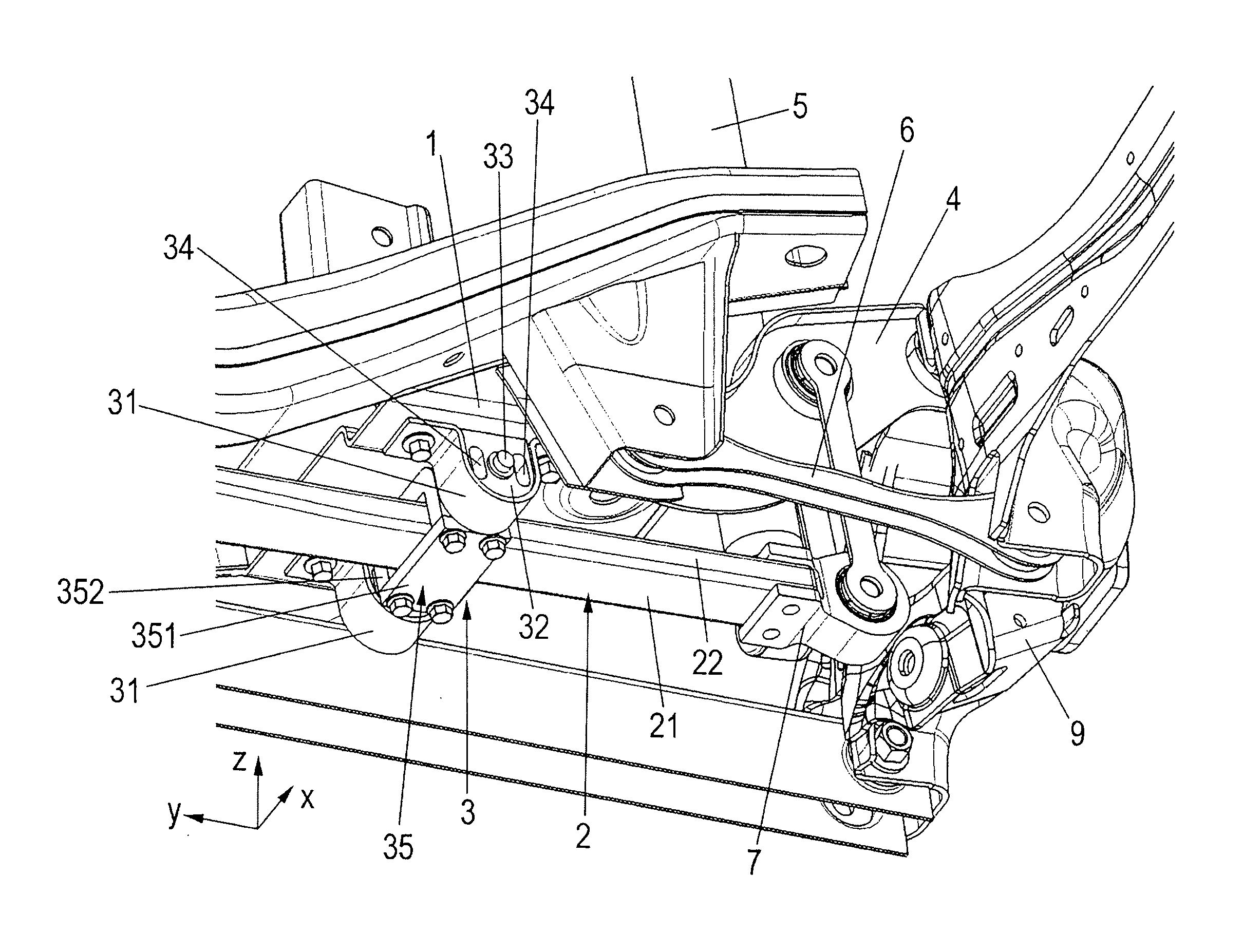
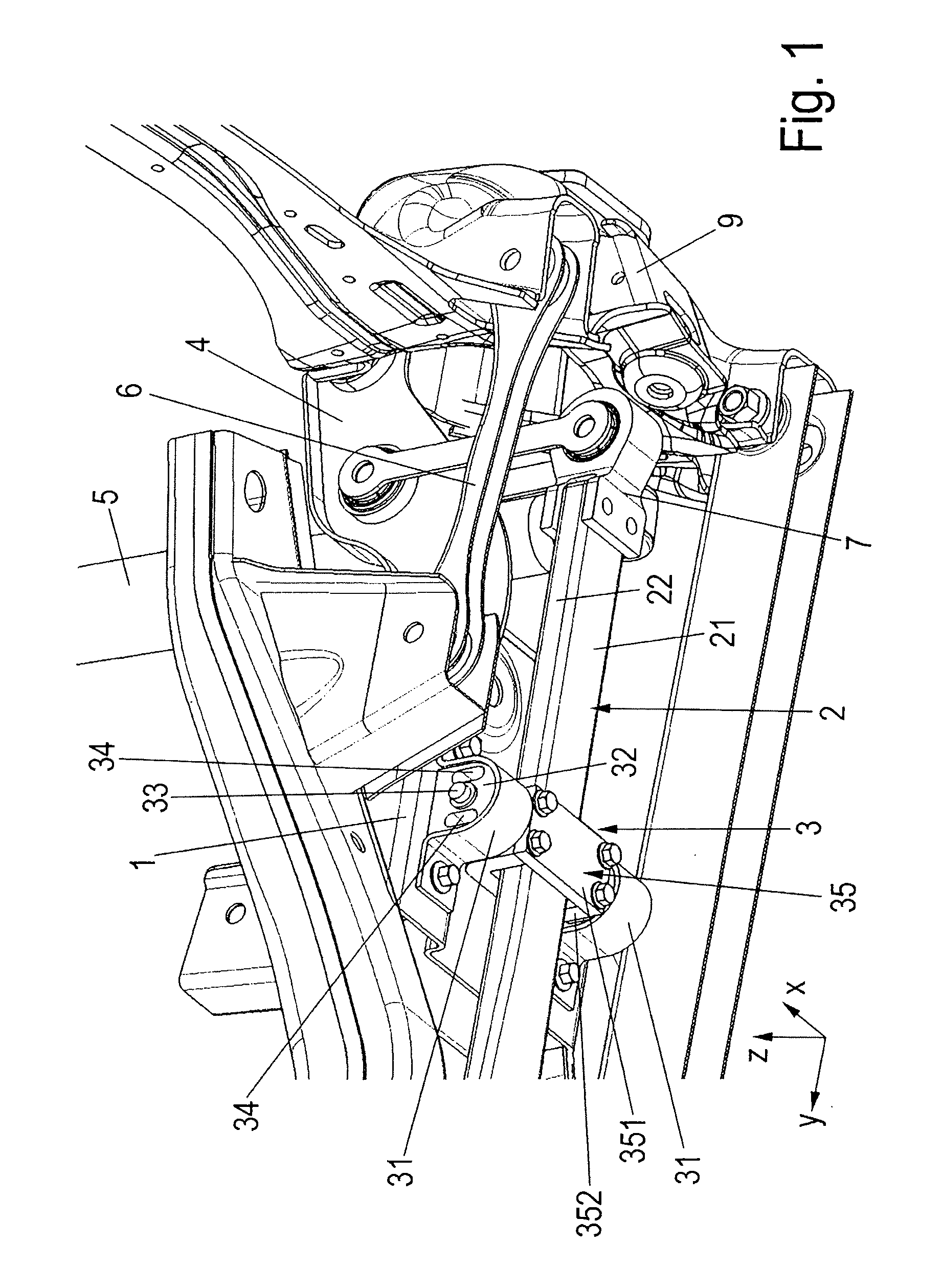
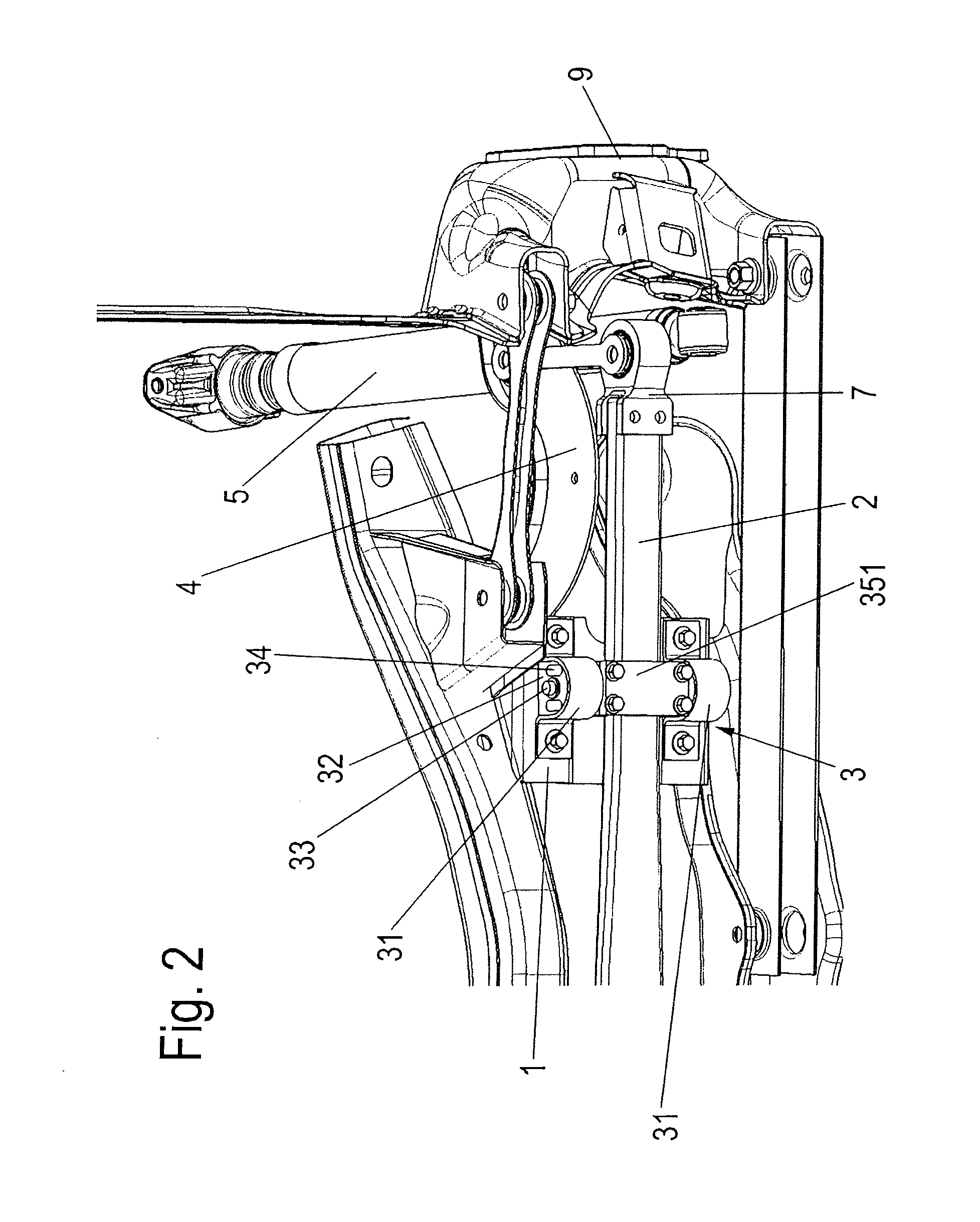
[0023]FIGS. 1 to 4 show a wheel suspension on a vehicle body 1, including a stub axle 9 and suspension arms 4, 6. The wheel suspension may be a rear-axle suspension on which two or more rotatable wheels (not shown) are arranged. A transverse leaf spring 2 is arranged as the main spring of the wheel suspension.

[0024]This transverse leaf spring 2 may include a light composite material, for example, glass-fiber reinforced plastic.

[0025]The linkage of the transverse leaf spring 2 to the vehicle body 1, or an auxiliary frame, occurs by way of at l...


PUM


Abstract

A wheel suspension of a motor vehicle includes a transverse leaf spring arranged along a transverse axis of the motor vehicle. The transverse leaf spring is connected via two bearings with a body of the vehicle and is connected in an articulated manner at its two mutually opposite ends with a stub axle or suspension arm. The bearings are arranged such that the transverse leaf spring is stiffly fixed in a direction of a vertical axis of the vehicle and is movable in a translatory manner in a direction of the transverse axis of the vehicle and is rotationally movable around an axis that is parallel to a longitudinal axis of the vehicle.

Description

[0001]This application claims priority to German Patent Application No. 10 2010 060 093.8, filed Oct. 20, 2010, the content of which Applications are incorporated by reference herein.BACKGROUND AND SUMMARY[0002]The present disclosure relates to a wheel suspension of a motor vehicle. The wheel suspension includes a transverse leaf spring arranged along a transverse axis of a motor vehicle and which transverse leaf spring is connected via two bearings with a body of the vehicle and connected in an articulated manner at its two mutually opposite ends with a stub axle or a suspension arm.[0003]Coiled steel springs are mainly used in car manufacturing for suspending the car body. These steel springs are usually arranged close to the wheel irrespective of the configuration of the axle. In order to reduce rolling motions of the vehicle body, anti-roll bars made of steel are mostly used between the suspension points of an axle. Transverse leaf springs are also used for the suspension of the...

Claims


Application Information

Patent Timeline
Patent Type & Authority Applications(United States)
IPC IPC(8): B60G7/00
CPCB60G2202/114B60G11/08B60G11/107B60G21/05B60G2204/121
Inventor HOCHAPFEL, ERIKEBBING, TOBIASREINEKE, HENDRIKVON DER KALL, JURGENSCHRODER, ALOYSDRABON, RODSCHASCHNABEL, CHRISTIANZUBER, ARMIN
Owner BENTELER AUTOMOBILTECHNIK GMBH
Why Eureka
Try Eureka