

Quadrature power amplifier architecture
a power amplifier and quadrature technology, applied in the direction of amplifier combinations, gated amplifiers, gain control, etc., can solve the problem that the receiver in such a transceiver does not operate simultaneously, and achieve the effect of simplifying the quadrature rf pa architecture, stable input impedance, and stable input impedan
- Summary
- Abstract
- Description
- Claims
- Application Information
AI Technical Summary
Benefits of technology
Problems solved by technology
Method used
Image

Examples
Embodiment Construction
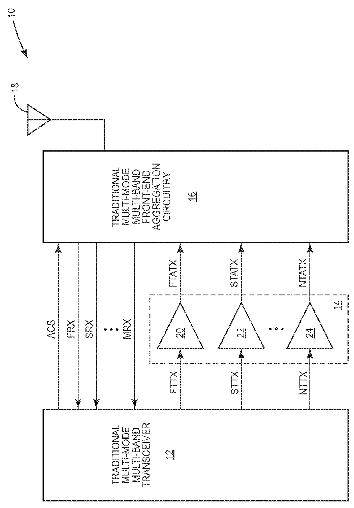
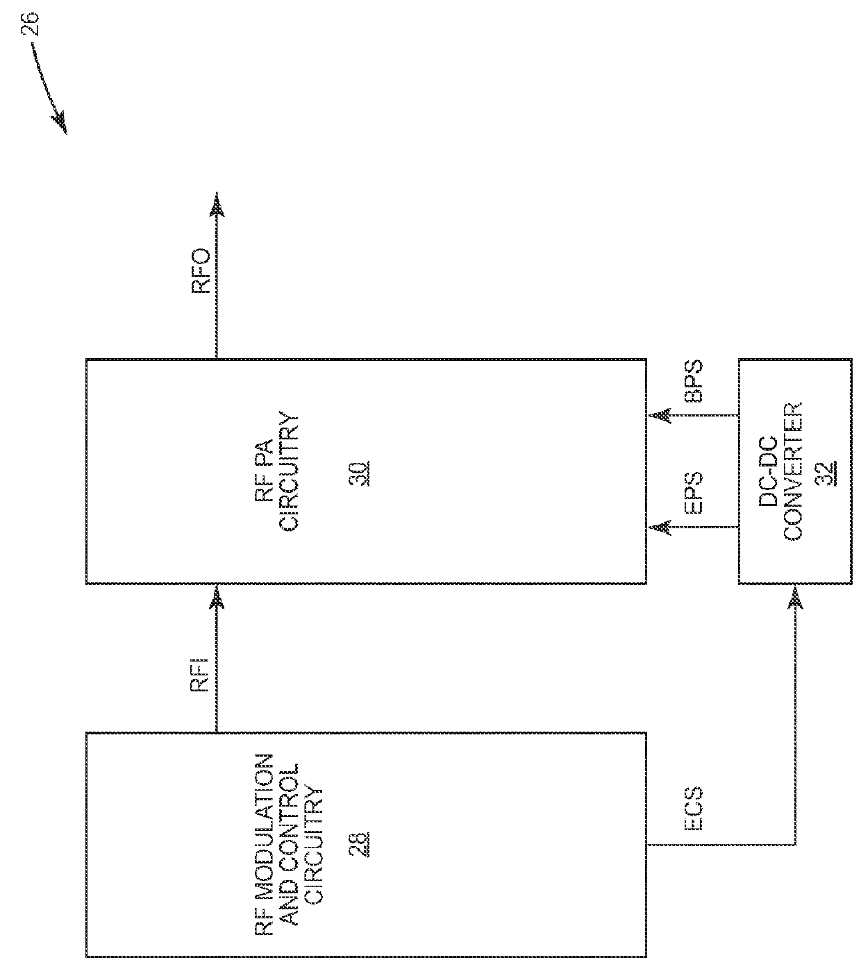
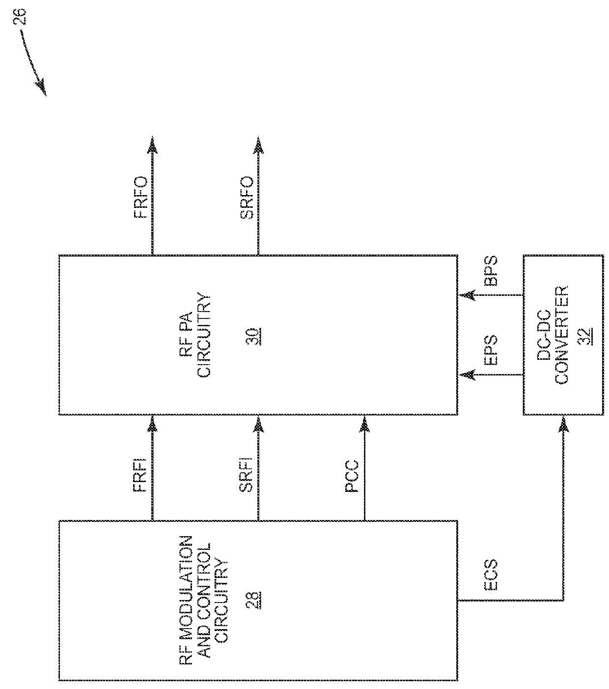
[0010]The present disclosure relates to a quadrature RF power amplifier (PA) architecture that utilizes a single-ended interface to couple a non-quadrature PA path to a quadrature PA path, which may be coupled to an antenna. The quadrature nature of the quadrature PA path may provide tolerance for changes in antenna loading conditions. An RF splitter in the quadrature PA path may present a relatively stable input impedance, which may be predominantly resistive, to the non-quadrature PA path over a wide frequency range, thereby substantially isolating the non-quadrature PA path from changes in the antenna loading conditions. Further, the input impedance may substantially establish a load line slope of a feeder PA stage in the non-quadrature PA path, thereby simplifying the quadrature RF PA architecture. One embodiment of the quadrature RF PA architecture uses two separate PA paths, either of which may incorporate a combined non-quadrature and quadrature PA architecture.
[0011]Due to t...
PUM
 Abstract
Description
Claims
Application Information