
Alignment film for spontaneously aligning liquid crystal

a liquid crystal and aligning film technology, applied in non-linear optics, instruments, optics, etc., can solve the problems of reducing yield, insufficient alignment stability and anchoring ability, and insufficient alignment stability, so as to prevent contamination problems, solve effective conventional problems, and reduce costs

Inactive Publication Date: 2012-04-26
NATIONAL TSING HUA UNIVERSITY
View PDF2 Cites 1 Cited by
  • Summary
  • Abstract
  • Description
  • Claims
  • Application Information

AI Technical Summary

Benefits of technology

[0004]The primary objective of the present invention is to solve the problems occurring in the conventional liquid crystal alignment technologies, including problems of dust pollution, complicated procedures and high cost.
[0005]To achieve the abovementioned objective, the present invention provide a liquid crystal spontaneous alignment film, which comprises a first substrate, a second substrate, a liquid crystal layer, a first transparent conductive layer, a second transparent conductive, a first alignment film, and a second alignment film. The second substrate is arranged opposite to the first substrate. The liquid crystal layer is interposed between the first and second substrates and consists of a plurality of liquid crystal grains. The first transparent conductive is arranged between the first substrate and the liquid crystal layer. The second transparent conductive layer is arranged between the second substrate and the liquid crystal layer. The first alignment film is arranged between the first transparent layer and the liquid crystal layer. The first alignment film is made of anodic aluminum oxide (AAO) and has a plurality of nanometric pores contacting the liquid crystal layer. The second alignment film is arranged between the second transparent conductive layer and the liquid crystal layer. The second alignment film is also made of anodic aluminum oxide and has a plurality of nanometric pores contacting the liquid crystal layer. The nanometric pores of the first and second alignment films induce the crystal liquid grains to align spontaneously.
[0006]The present invention prevents the contamination problem occurring in the conventional PI rubbing alignment method. The alignment film of the present invention is fabricated on the ITO glass substrate used in the common LCD process with only an additional electrochemical etching process rather than fabricated by expensive equipments. Thus, the fabrication process of the present invention is much simpler than that of the conventional optical alignment method, ion beam alignment method, or structural alignment method. Therefore, the present invention can effectively solve the conventional problems.

Problems solved by technology

For example, the rubbing process may generate dust, residual electrostatic charge, scratches and non-uniform alignment, which are all likely to decrease the yield.
Although the optical alignment method is a non-contact type alignment technology and prevents the problems of the contact type methods, it also has its own problems.
Further, the alignment stability and anchoring ability thereof is insufficient.
Although the ion beam alignment method prevents dust contamination like the contact type alignment methods, it is expensive and needs complicated equipment.
Further, the service life of the ion gun is short.
Although the structure alignment method can fast mass-produce large-size LCD and reduce the fabrication cost, it still has problems of contamination, complicated procedures and non-uniform alignment, which are likely to reduce the yield.

Method used


Image

  • Alignment film for spontaneously aligning liquid crystal
  • Alignment film for spontaneously aligning liquid crystal
  • Alignment film for spontaneously aligning liquid crystal

Examples


first embodiment

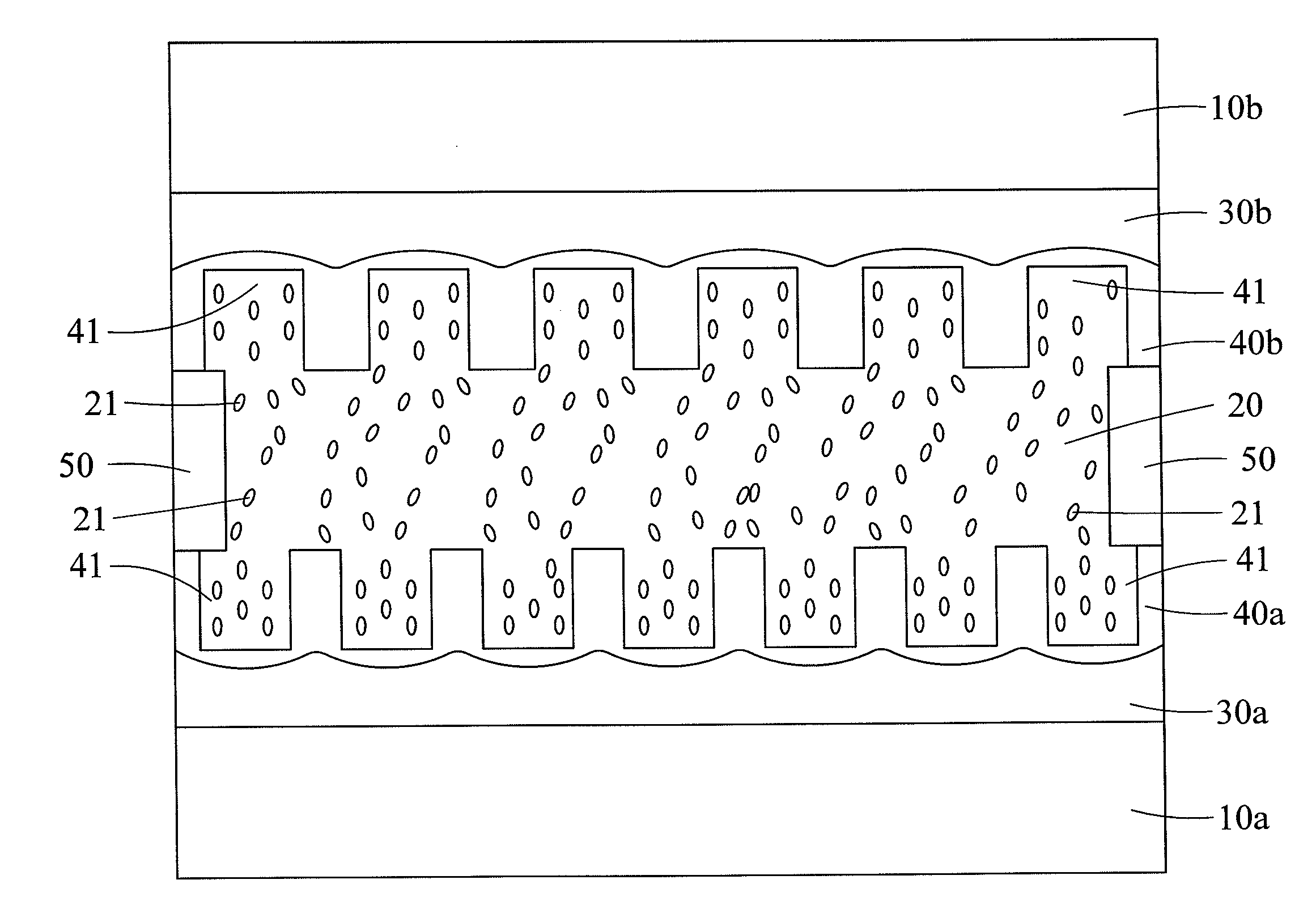
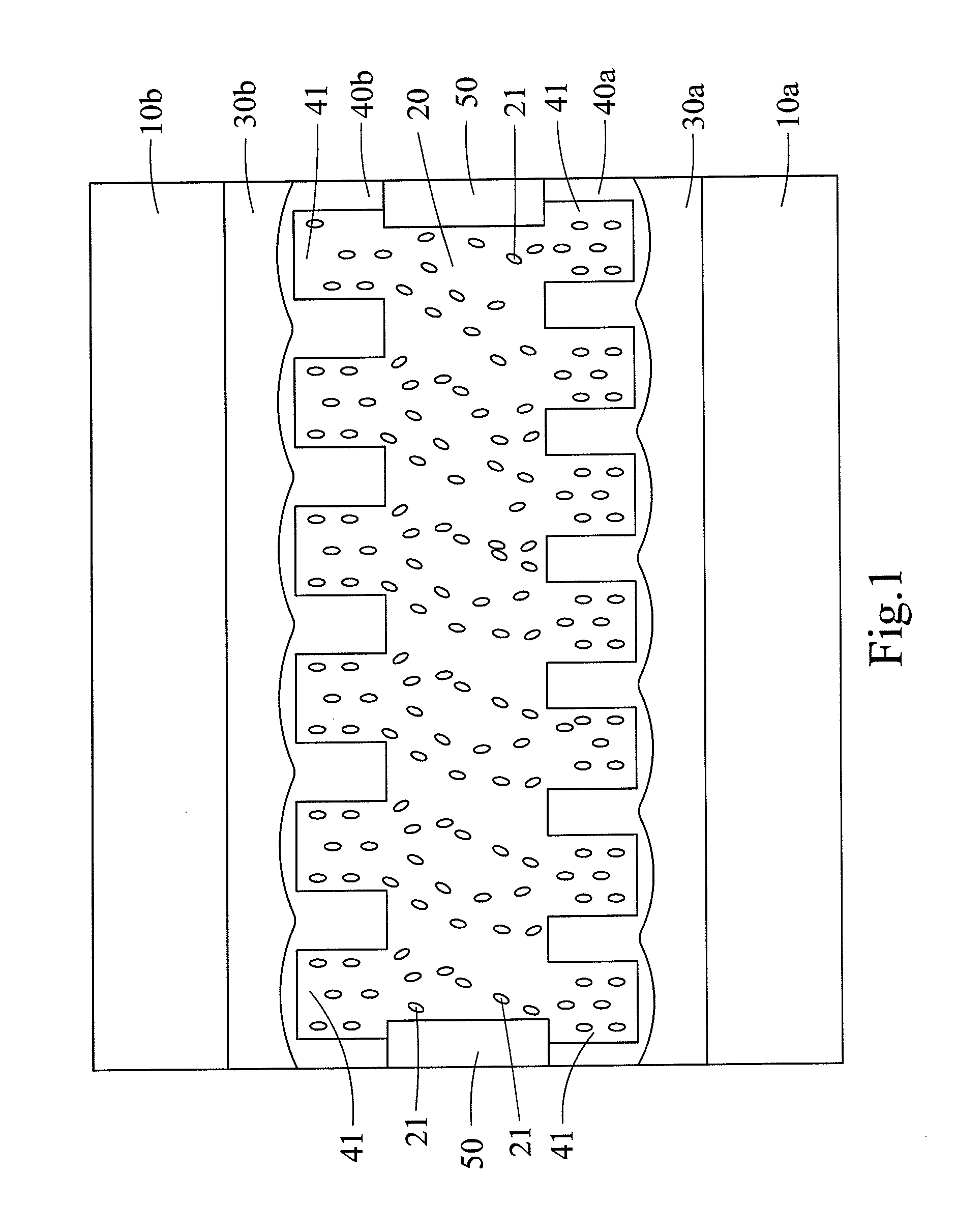
[0013]Refer to FIG. 1 a cross sectional view showing the structure of an alignment film for spontaneous aligning liquid crystal according to the present invention. The alignment film of the present invention is used to align a plurality of liquid crystal grains 21 and comprises a first substrate 10a, a second substrate 10b, a liquid crystal layer 20, a first transparent conductive layer 30a, a second transparent conductive layer 30b, a first alignment film 40a and a second alignment film 40b.

[0014]The second substrate 10b is arranged opposite to the first substrate 10a. The liquid crystal layer 20 is interposed between the first and second substrates 10a and 10b and consists of a plurality of liquid crystal grains 21. The first transparent conductive layer 30a is arranged between the first substrate 10a and the liquid crystal layer 20. The second transparent conductive layer 30b is arranged between the second substrate 10b and the liquid crystal layer 20. The first alignment film 4...

second embodiment

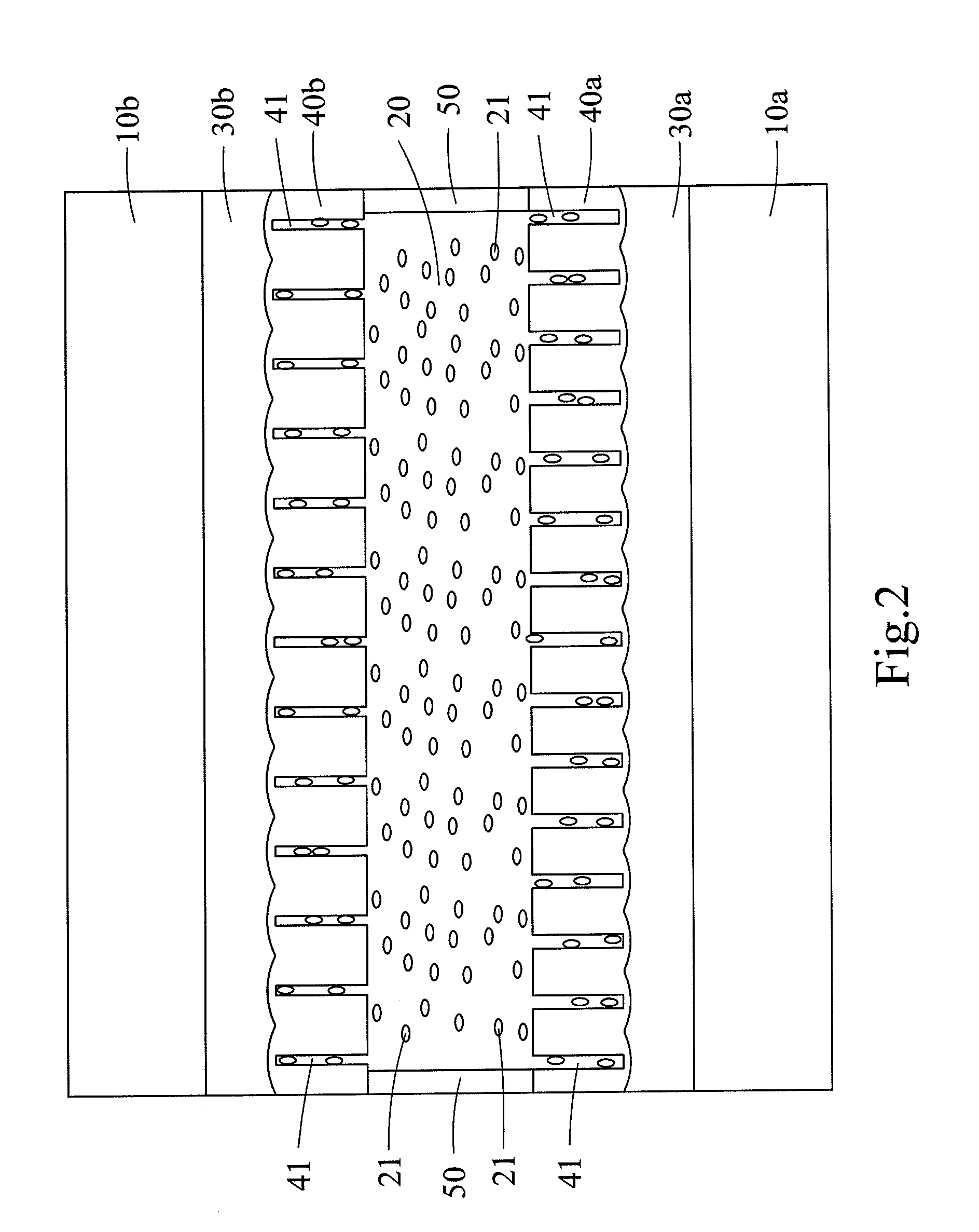
[0015]Refer to FIG. 2 a cross sectional view showing that nanometric pores induce horizontal alignment of liquid crystal grains according to the present invention. In the present invention, the nanometric pores 41 align the liquid crystal grains 21 via applying the capillary action and the gravitational action on the liquid crystal grains 21 and influencing the collective behavior of the liquid crystal grains 21. Therefore, the size of the nanometric pores 41 correlates with the result of the alignment of the liquid crystal grains 21.

[0016]More specifically when the size of the nanometric pores 41 is between 5 and 80 nm, the liquid crystal grains 21 inside the nanometric pores 41 are aligned vertically by the capillary action and the gravitational action. The liquid crystal grains 21 inside the nanometric pores 41 thus have a vertical-alignment topography and interact with the liquid crystal grains 21 outside the nanometric pores 41. Thereby, the liquid crystal grains 21 outside the...


PUM


Abstract

An alignment film for spontaneously aligning liquid crystal is used to align a plurality of liquid crystal grains and comprises a first substrate, a second substrate, a liquid crystal layer, a first transparent conductive layer, a second transparent conductive layer, a first alignment film and a second alignment film. The first and second alignment films are made of anodic aluminum oxide and have a plurality of nanometric pores respectively. The liquid crystal layer is interposed between the first and second alignment films. The nanometric pores of the first and second alignment films induce the liquid crystal grains to align spontaneously. Thereby, the problems of contamination, denatured material and non-uniform alignment, which are caused by the conventional liquid crystal alignment technology, can be solved. Further, the fabrication process of the alignment film can integrate with the current LCD process to fabricate a large-size LCD panel.

Description

FIELD OF THE INVENTION[0001]The present invention relates to a liquid crystal alignment device, particularly to a liquid crystal alignment film.BACKGROUND OF THE INVENTION[0002]The conventional liquid crystal (LC) alignment technology for liquid crystal displays includes the PI rubbing alignment method, the optical alignment method, the ion beam alignment method, and the structure alignment method. Among them, the PI rubbing alignment method is used in mass production currently. The PI rubbing method is a contact type alignment method, wherein a flannel roller applies directional mechanical rubbing actions to the surface of polyimide (abbreviated as PI) to induce liquid crystal alignment. The PI rubbing alignment method is superior for the purposes of mass production. However, it also has many disadvantages. For example, the rubbing process may generate dust, residual electrostatic charge, scratches and non-uniform alignment, which are all likely to decrease the yield.[0003]The opti...

Claims


Application Information

Patent Timeline
IPC IPC(8): G02F1/1337
CPCG02F1/133707
Inventor HUNG, CHI-TSUNGTANG, TSUNG-TAHUNG, CHI-YUANCHAO, RU-PINFANG, WEI-LEUN
Owner NATIONAL TSING HUA UNIVERSITY
Learn More