Medical imaging device

a medical imaging and device technology, applied in the field of medical imaging, can solve the problems of inability to easily see subcutaneous veins on patients, variations in skin tone, body fat and other physical characteristics, and devices are not always effective in locating veins, etc., and achieve the effect of simple and rapid exchange of light heads and minimal configuration

Inactive Publication Date: 2012-04-26
SOLVONICS
View PDF99 Cites 24 Cited by
  • Summary
  • Abstract
  • Description
  • Claims
  • Application Information

AI Technical Summary

Benefits of technology

[0024]In a preferred embodiment of the present invention, the control circuit includes a mode selection feature for choosing the manner in which the two sets of LEDs are illuminated. For example, in one mode, the control circuit causes the first set of LEDs to be illuminated continuously, without perceptible variation in intensity, while periodically modulating the intensity of the second set of LEDs in a gradual fashion. The resulting light emitted by the second set of LEDs takes on a pulsed appearance, enhancing the visibility of subcutaneous tissues, and effectively providing a depth-of-field image of such subcutaneous tissues. Preferably, the intensity of the second set of LEDs is varied by modulating the pulse width of electrical pulses used to turn on the second set of LEDs.
[0027]Preferably, the control circuit includes a microcontroller programmed with firmware to determine the manner in which the different sets of LEDs are illuminated. If desired, such firmware may be re-programmed from time to time to alter the illumination modes initially programmed into the microcontroller. A mode selection switch allows a user to select a mode that best suits the physiology of the patient being treated.
[0030]In one preferred form of the present invention, the light head is provided as a minimal configuration element which essentially includes only the first and second sets of LEDs, physical support for such LEDs, and electrical conductors for routing the electrical signals to such LEDs to illuminate them in the manner described above. A separate base unit incorporates the above-described control circuit and a source of electrical power. A connection cord extends between the base unit and the light head to provide driving electrical signals that illuminate the LEDs in the desired manner. The light head includes an electrical connector for allowing the connection cord to be removably attached thereto. By providing the light head in such a minimal configuration form, the cost and complexity of each light head is minimized. The cost may actually be low enough to allow such light heads to be disposable, avoiding the need to sterilize the light head or otherwise guard against contamination of the light head from one patient to the next. Alternatively, by providing the light head in such a minimal configuration form, sterilization of the light head, as by autoclaving, between uses is simplified.
[0031]Another alternative to avoid the need to sterilize the light head, while minimizing the portion which is discarded, is to provide a protective plastic cover which may be clipped onto the light head prior to its use on a patient, and which prevents blood or other fluids from making contact with the first and second sets of LEDs, the supporting members, and the electrical conductors. An important aspect of the head design is the manner in which light is channeled from the LEDs to the skin surface. In the disposable cover case, clear windowing can be incorporated with lens and or diffuser characteristics. Incorporating lenses into the disposable cover provides an inexpensive method to allow focal and diffusion characteristic options that may be tailored to the patient's tissue characteristics. In this preferred embodiment, a printed circuit board includes a series of electrical conductors. A first set of LEDs of one color, and a second set of LEDs of a different color, are supported upon the lower surface of the printed circuit board and electrically coupled to the electrical conductors of the printed circuit board. A pc board support member, having a shape generally matching that of the printed circuit board, receives the printed circuit board, while having one or more apertures aligned with the LEDs for allowing light emitted by such LEDs to pass therethrough.
[0033]The lower cost of minimal configuration light heads facilitates providing two or more different styles of light heads, each incorporating a different profile and / or different pattern of LEDs. Each of such different styles of light heads is adapted to be connected to the same base unit, allowing for simple and rapid exchange of such light heads when required by the circumstances. Different styles of light heads may be better suited to visualize different subcutaneous features, yet all of such light heads may be driven by the same base unit. For example, a light head for pediatric use may be of smaller size, and perhaps include a smaller number of LEDs. Of course, a base unit may be used in conjunction with two or more light heads of the same type or style, particularly if such light heads are disposable after single-use application, or if two or more patients co-incidentally require the use of such medical imaging device at approximately the same time.
[0034]In an alternate embodiment, the light head is provided in the form of a stand-alone case that contains the aforementioned LED control circuit and a power source, e.g., a battery. In this alternate embodiment, the base unit is essentially used to re-charge the light head. Preferably, the base unit includes its own higher-capacity battery, and can be plugged into an AC outlet for rapid recharging of its higher-capacity battery. The base unit includes a docking port adapted to receive the light head when the light head is not in use. When the light head is docked with the base unit, electrical connections therebetween allow the battery with a relatively greater amp-hour capacity in the base unit to charge the battery with relatively lesser amp-hour capacity in the light head. Thus, the light head may be charged in the base unit for its next use, even if the base unit is not plugged into an AC outlet. Once the battery in the light head is re-charged, the light head is removed, or un-docked, from the base unit and is ready for use.

Problems solved by technology

However, such devices are not always effective for locating veins due to the high variability in the absorption and scattering of visible light within human tissue of patients.
Difficulties often result from variations in skin tones, body fat, and other physical characteristics.
However, even using visible light at the longest possible wavelengths, subcutaneous veins are not always easily visible on every patient for a variety of reasons.
As an example, patients with darker skin color are known to be more difficult to illuminate, possibly due to the absorption of light by the melanin which creates darker skin tones.
Additionally, veins in obese patients are also known to be more difficult to trans-illuminate due to the increased amount of fatty tissue surrounding the vein, which serves to scatter the emitted light and obscure the subcutaneous veins.
In addition, while portable vein imaging devices like the above-described VEINLITE LED® device are pocket-sized, the case is still relatively bulky, particularly when a nurse or medical technician is trying to stabilize the device with one hand while placing a vein puncture needle with the other hand.
Moreover, the ring design of the LED light head illuminates only a small portion of a vein at a time, and the relatively small portion of the ring that is left open is insufficient to permit convenient placement of a vein puncture needle within the vein, once the vein is located.
Since simple LED based trans-illumination devices are not always effective in making veins easy to locate, alternate technologies are employed for the purpose of vein location.
Imaging devices using infrared (IR) radiation are also very popular, but are inherently more costly and difficult to use.
Thus, IR systems require much more sophisticated electronics, and furthermore result in the health care provider necessarily viewing a projected image of the tissue, rather than the tissue itself.
However, like the IR systems discussed above, ultrasound technology is far more costly and difficult to use than a simple LED based trans-illumination device.
Furthermore, ultrasound technology by its nature is able to image deeply within human tissue, but is often ineffective for imaging near the skin's surface.
Thus, ultrasound systems may in fact have difficulty imaging the most accessible veins near the skin's surface.
However, it would be overly expensive if a hospital, clinic, or other medical facility had to have on-hand separate medical imaging devices for different applications, each with its own power source and controller circuitry.

Method used


Image

  • Medical imaging device
  • Medical imaging device
  • Medical imaging device

Examples


Embodiment Construction

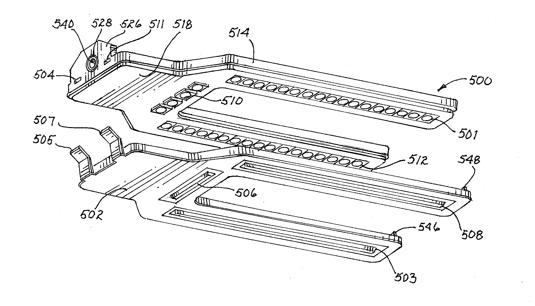
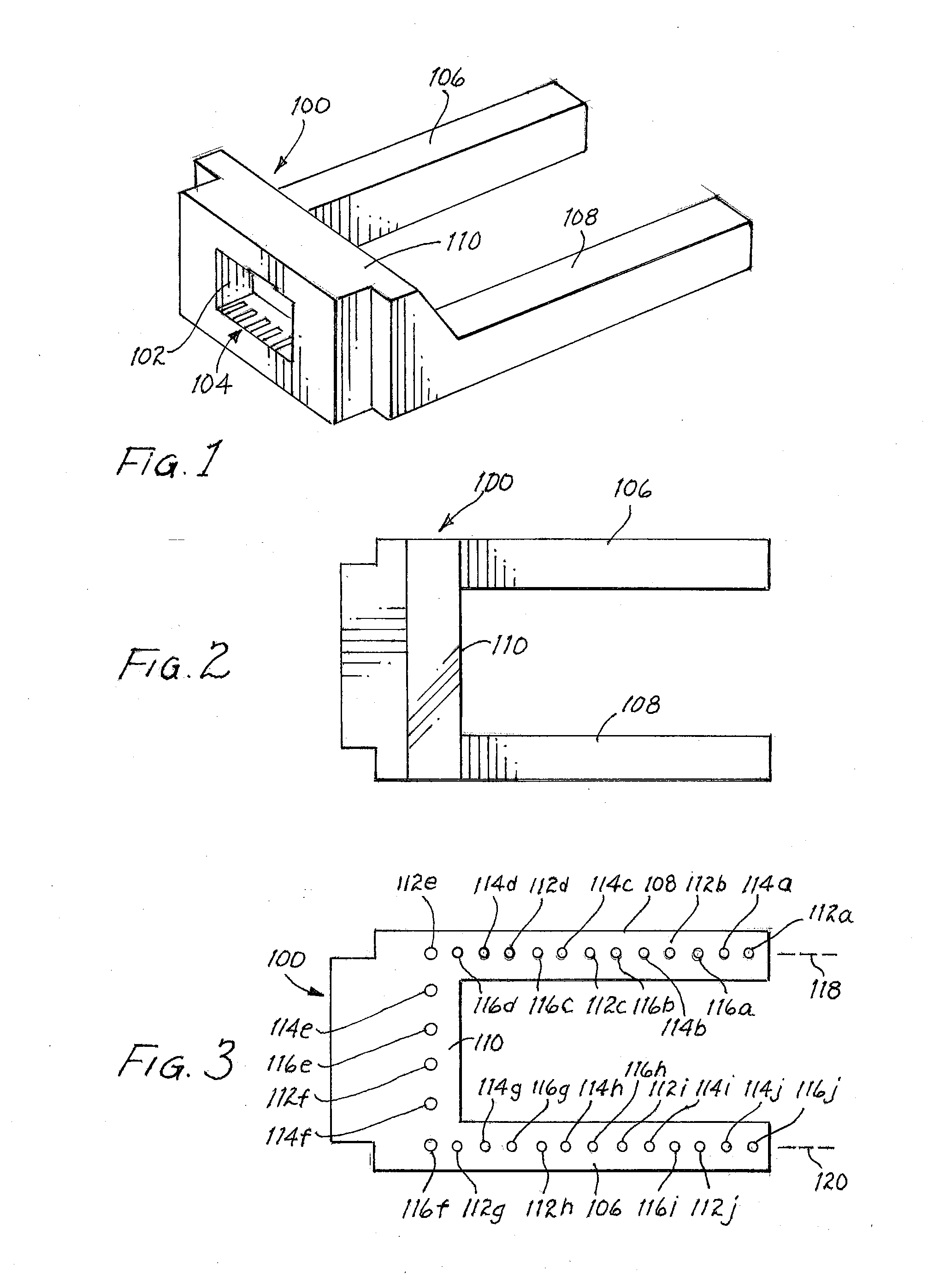
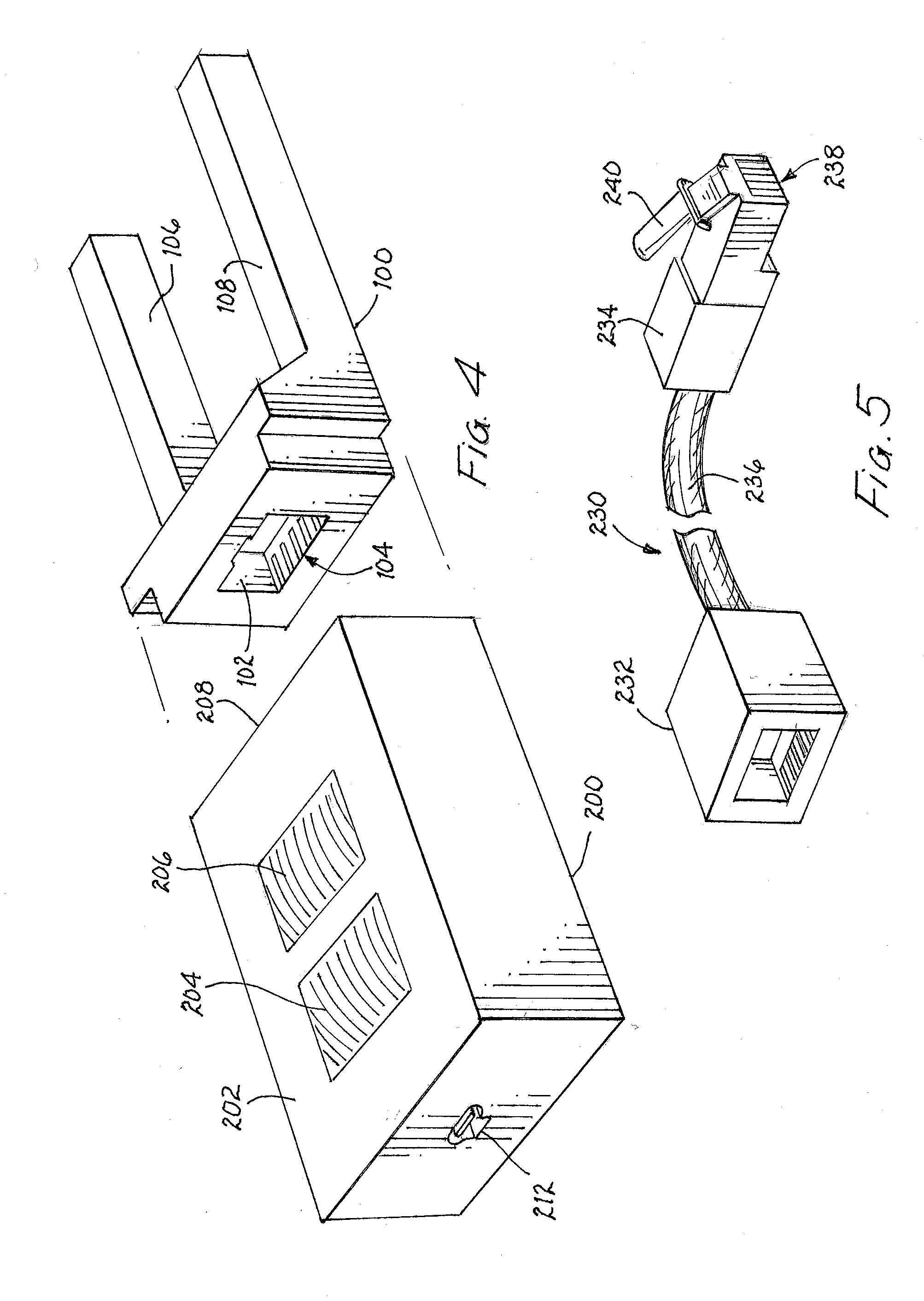
[0055]In FIG. 1 of the drawings, an LED light head for trans-illuminating veins or other subcutaneous tissues is designated generally by reference numeral 100. Light head 100 includes a recess 102 in which a multiple-conductor electrical connector 104 is secured. Preferably, connector 104 is an RJ-11 style connector that conventionally includes six electrical contacts. Alternately, an audio jack type connector may be used in order to provide for a thinner profile for LED light head 100. FIG. 2 is a top view of light head 100 and shows first and second arms, or bars, 106 and 108 spaced apart from each other, and extending generally parallel to each other. A central connecting element 110 is coupled to first ends of arms 106 and 108 and secures them together. Thus, light head 100 generally has a horse-shoe, or goalpost, shaped appearance.

[0056]FIG. 3 shows the underside of light head 100 of FIGS. 1 and 2. In FIG. 3, a series of ten red-colored LEDs 112a, 112b, 112c, 112d, 112e, 112f, ...


PUM


Abstract

A trans-illumination device includes at least first and second sets of LEDs of two or more different colors arranged in a light head placed against a patient's skin. The LEDs are mounted to a printed circuit board in the light head. An electronic control circuit is coupled to the light head by an electrical cable to selectively operate the LEDs in two or more user-selected modes, with the ability to adjust the relative intensities of the different colors to best suit the physiology of the patient. The light head may have a U-shape to surround an area of interest while providing ready access thereto. The light head may be used with a disposable, detachable cover having lenses for directing light from the LEDs into the patient's tissues.

Description

CROSS REFERENCE TO RELATED APPLICATIONS[0001]This application claims the benefit of the earlier filing date of U.S. provisional patent application No. 61 / 405,543, entitled “Medical Imaging Device”, filed on Oct. 21, 2010, by the same inventors named herein, pursuant to 35 USC §119(e). This application also claims the benefit of the earlier filing date of U.S. provisional patent application No. 61 / 405,532, entitled “Pediatric Tissue Illuminator”, filed on Oct. 21, 2010, by the same inventors named herein, pursuant to 35 USC §119(e).FIELD OF THE INVENTION[0002]The present invention relates generally to the field of medical imaging, and more particularly to the illumination of veins and other tissues in the body.BACKGROUND OF THE INVENTION[0003]In order to safely and effectively administer intravenous (IV) lines, or draw blood from a patient, it is critical for the health care provider to be able to locate suitable veins. In many instances, experienced medical personnel are able to loc...

Claims


Application Information

Patent Timeline
Patent Type & Authority Applications(United States)
IPC IPC(8): A61B1/06
CPCA61B5/489
Inventor DUFFY, THOMAS P.HARDER, GERALD T.MORI, KEVIN
Owner SOLVONICS
Why Eureka
Try Eureka