Percutaneously implantable flap stent, device for applying the same and method for producing the flap stent

a technology of percutaneous implantation and flap stent, which is applied in the field of valve stent, can solve the problems of disadvantage of previously described stents, inability to extend the treatment range of patients, and insufficient adaptation of stents to biomechanics and anatomy, etc., and achieves the effect of minimal material use and maximum stiffness

Active Publication Date: 2012-04-26
BIOLNIC UG
View PDF6 Cites 70 Cited by
  • Summary
  • Abstract
  • Description
  • Claims
  • Application Information

AI Technical Summary

Benefits of technology

[0011]It is therefore a task of the present invention to create a valve stent designed in such a way that it has maximum stiffness with minimum use of materials.

Problems solved by technology

This complicated procedure is carried out with the aid of heart-lung machines and is to some extent not an option for high-risk patients.
However, these stents are not or only insufficiently adapted to the biomechanics and anatomy of highly stressed heart- or venous valve prostheses.
The previously described stents are disadvantageous as a result of their stiffness under forces directed radially inwards.
Although it is possible in principle to increase the stiffness of a stent using more supporting material, this results in an adverse increase of the area of extraneous material within the blood vessels.
This increases the risk of thrombotic accumulations, for example.

Method used


Image

  • Percutaneously implantable flap stent, device for applying the same and method for producing the flap stent
  • Percutaneously implantable flap stent, device for applying the same and method for producing the flap stent
  • Percutaneously implantable flap stent, device for applying the same and method for producing the flap stent

Examples


Embodiment Construction

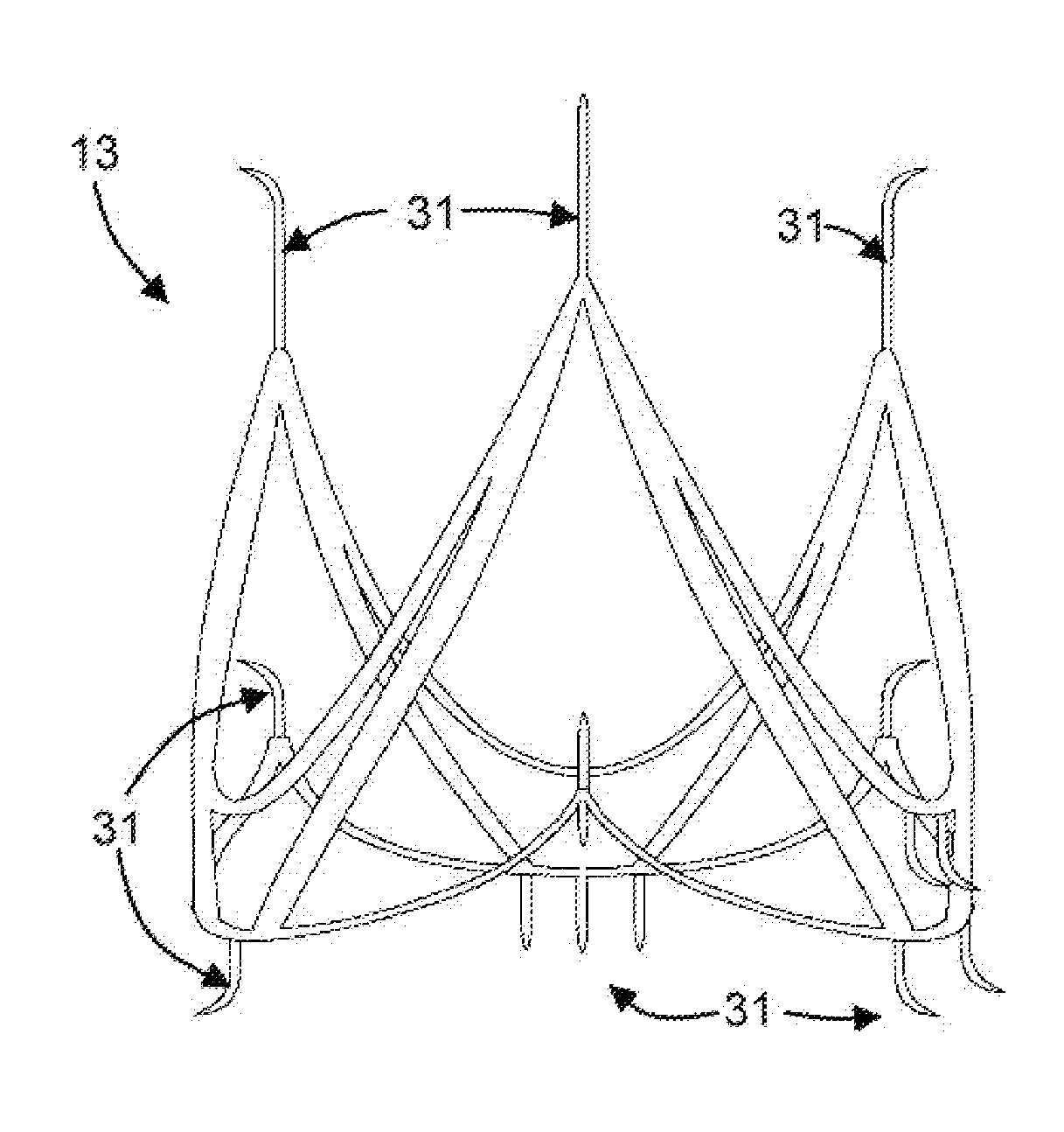
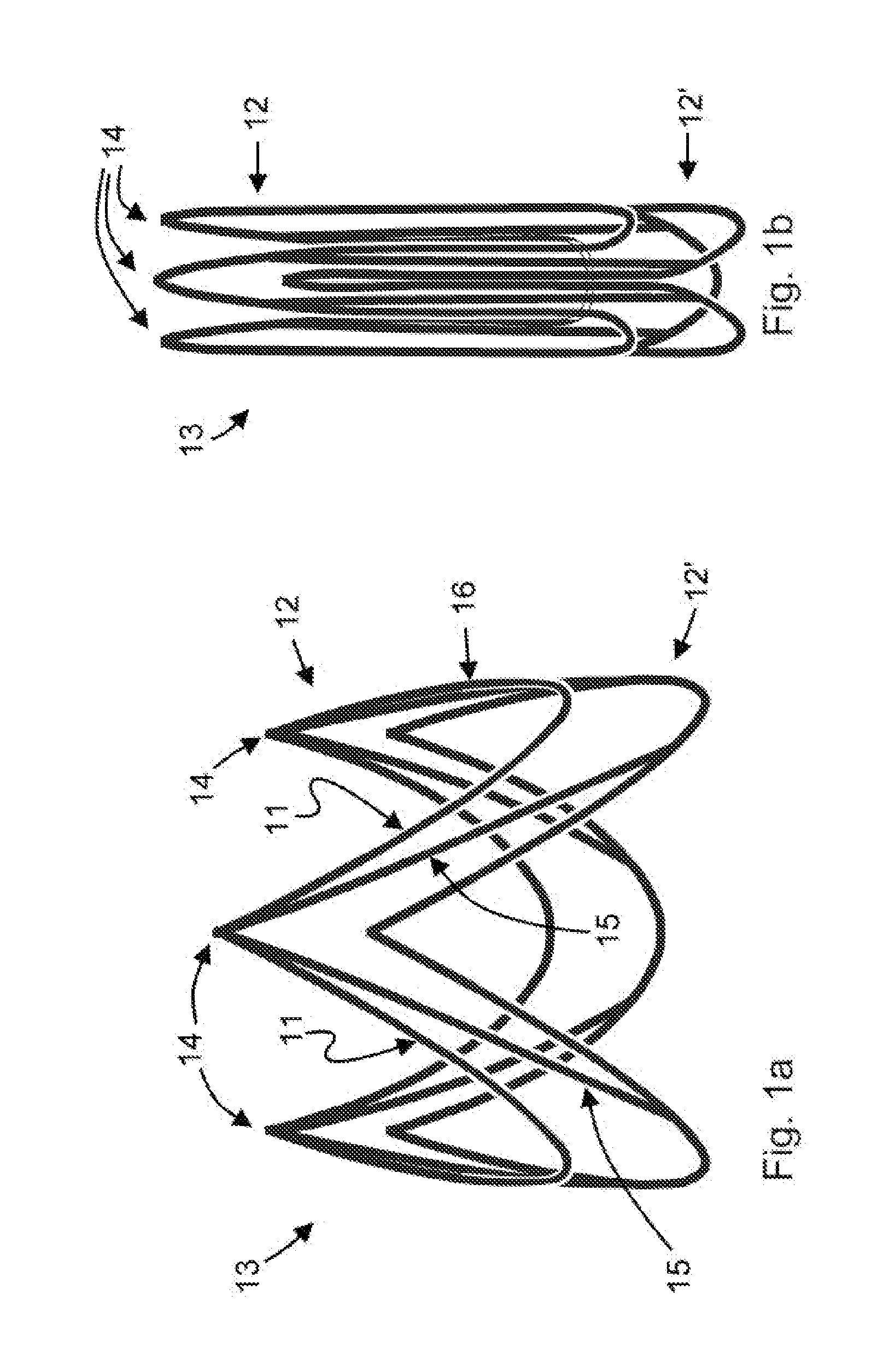
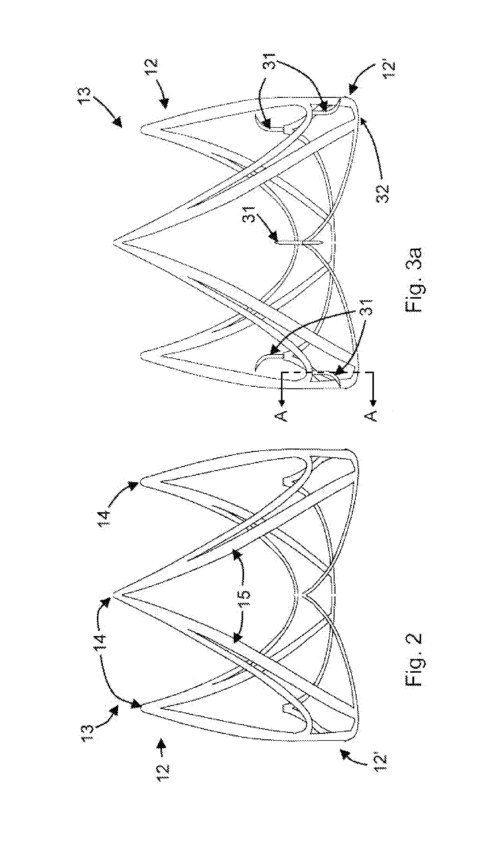
[0038]According to a preferred design of the present invention, as shown in FIG. 1a, for example, it is intended that each of three u-shaped bends 11 are connected to each other at the ends 14 to form a crown element 12. In principle, two or more than three u-shaped bends 11 can be designed. Preferably, two or more crown elements 12 arranged one behind the other form a valve stent 13. Overall, the edge geometry of the leaflets, i.e. the connection line from the valve leaflets to the stent, which is similar to a three-pronged crown, ensures a low and even stress distribution in the leaflets. The clamp forces directed radially inwards are thereby absorbed by the stent, without radial deformation of the ends (commissures) 14 of the valve leaflets towards the inside, which facilitates the opening and closing movement of the leaflets.

[0039]Moreover, the preferred stent design features an anatomically adapted design in a natural subanular position. Thus, the aortic bulbs, which are bulbou...


PUM


Abstract

A valve stent includes a plurality of crown elements arranged coaxially one behind the other, each formed by several u-shaped bends with at least one base and two ends. The bases of one crown element are connected to the ends of another crown element via connection bars. To produce this valve stent, 3D droplet dosing technology is used to form a thin-walled sandwich structure. A device, suitable for application of a stent is provided with positioning wires having clamps at their ends which can be connected to the fixing hooks at the ends of the crown elements in force-locking manner.

Description

CROSS REFERENCE TO RELATED APPLICATIONS[0001]This application is a United States National Phase application of International Application PCT / DE2010 / 000729 and claims the benefit of priority under 35 U.S.C. §119 of German Patent Application DE 10 2009 031 173.4 filed Jun. 29, 2009, German Patent Application DE 10 2009 037 739.5 filed Aug. 17, 2009, the entire contents of which are incorporated herein by reference.FIELD OF THE INVENTION[0002]The present invention relates to a valve stent composed of a plurality of crown elements that are arranged coaxially one behind the other and each formed by several u-shaped bends with at least one base and two ends. Furthermore, the present invention relates to a device for the application of a stent as well as the process for making a valve stent to take up polymeric valve leafletsBACKGROUND OF THE INVENTION[0003]Surgical heart valve replacement is usually carried out on a cardioplegic (arrested) heart. The affected heart valve is cut out and th...

Claims


Application Information

Patent Timeline
Patent Type & Authority Applications(United States)
IPC IPC(8): A61F2/82B05D5/00A61F2/848A61F2/95
CPCA61F2/2418A61F2/2436A61F2002/30329A61F2002/8483A61F2002/8486A61F2230/0054A61F2220/0025A61F2250/006A61F2220/0008A61F2220/005A61F2002/9522A61F2/9522A61F2/2475A61F2/2412
Inventor JANSEN, JOSEF
Owner BIOLNIC UG
Why Eureka
Try Eureka