Heat Pipe, Method For Manufacturing A Heat Pipe, And A Circuit Board With A Heat Pipe Function

a technology of heat pipe and heat pipe, which is applied in the direction of electrical apparatus casing/cabinet/drawer, instrument, and semiconductor/solid-state device details, etc., can solve the problem that the heat pipe does not prevent the high-density packaging

Inactive Publication Date: 2012-05-03
FUCHIGAMI MICRO +1
View PDF15 Cites 14 Cited by
  • Summary
  • Abstract
  • Description
  • Claims
  • Application Information

AI Technical Summary

Benefits of technology

[0011]Accordingly, the purpose of the Present Application is to provide a heat pipe that does not prevent the high-density packaging and is excellent at cooling effects, a method for manufacturing the heat pipe, and a circuit board having the heat pipe function.
[0013]The Present Application can realize a heat pipe that is flat plate-like and enables a cooling medium to circulate in both the perpendicular direction and the flat surface direction for heat transfer at a high speed. In addition, the Present Application can form a via hole having an extremely small diameter in a heat pipe without adversely influencing the strength and durability of the heat pipe. Moreover, electronic parts can be electronically connected to each other through a via hole provided in a heat pipe, whereby the use of a heat pipe does not prevent the high-density packaging. Additionally, electronic parts can be cooled and mounted at the same time.
[0017]In addition, the heat pipe is characterized in that at least one of the upper plate, the lower plate and the intermediate plates is constituted of a plurality of members, the members being able to be bonded together in the thickness direction. This configuration enables to further reduce the diameter of an external through-hole penetrating any one of the upper plate, the lower plate and a plurality of the intermediate plates. As a result, the diameter of a via hole can be further reduced.
[0018]In addition, the heat pipe is characterized in that the heat pipe is manufactured, wherein: the upper plate having the external through-hole, the lower plate having the external through-hole and a plurality of the intermediate plates each having the internal through-hole and the external through-hole are overlaid on each other by sandwiching a plurality of the intermediate plates between the upper plate and the lower plate; the external through-hole formed in the upper plate, the external through-hole formed in the lower plate and the external through-holes formed in a plurality of the intermediate plates are superposed on each other to form a via hole, the via hole penetrating the upper plate all the way through the lower plate; and the internal through-holes formed in each of a plurality of the intermediate plates are adapted such that only part of each through-hole is overlapped on each other to form capillary tube paths, each having a cross-sectional area smaller than the cross-sectional area of the through-hole in the flat surface direction. This configuration enables to form a via hole having a minute diameter while complying with the processing limit. As a result of forming a minute via hole, a heat pipe that has no adverse influence on the high-density packaging can be achieved.
[0019]In addition, the heat pipe is characterized in that: each of a plurality of the intermediate plates comprises a notch section and a plate section; the notch section provided in each of a plurality of the intermediate plates is overlapped on each other to form a vapor diffusion path, the vapor diffusion path being an internal space; the vapor diffusion path diffuses a vaporized cooling medium generated by the vaporization of an enclosed cooling medium; and the capillary tube path circulates a condensed cooling medium generated by the condensation of the enclosed cooling medium. This configuration enables to circulate a cooling medium at a high speed and achieve a heat pipe excellent at the efficiency of heat transfer.
[0022]In addition, the heat pipe is characterized in that the heat pipe is a square of at least 20 square millimeters and not more than 100 square millimeters and has a thickness of at least 1 mm and not more than 5 mm. This configuration enables to achieve a heat pipe that can strike a balance between the cooling and the mounting.

Problems solved by technology

Moreover, electronic parts can be electronically connected to each other through a via hole provided in a heat pipe, whereby the use of a heat pipe does not prevent the high-density packaging.

Method used


Image

  • Heat Pipe, Method For Manufacturing A Heat Pipe, And A Circuit Board With A Heat Pipe Function
  • Heat Pipe, Method For Manufacturing A Heat Pipe, And A Circuit Board With A Heat Pipe Function
  • Heat Pipe, Method For Manufacturing A Heat Pipe, And A Circuit Board With A Heat Pipe Function

Examples


Embodiment Construction

[0037]While the Present Application may be susceptible to embodiment in different forms, there is shown in the Figures, and will be described herein in detail, specific embodiments, with the understanding that the disclosure is to be considered an exemplification of the principles of the Present Application, and is not intended to limit the Present Application to that as illustrated.

[0038]In the illustrated embodiments, directional representations—i.e., up, down, left, right, front, rear and the like, used for explaining the structure and movement of the various elements of the Present Application, are relative. These representations are appropriate when the elements are in the position shown in the Figures. If the description of the position of the elements changes, however, it is assumed that these representations are to be changed accordingly.

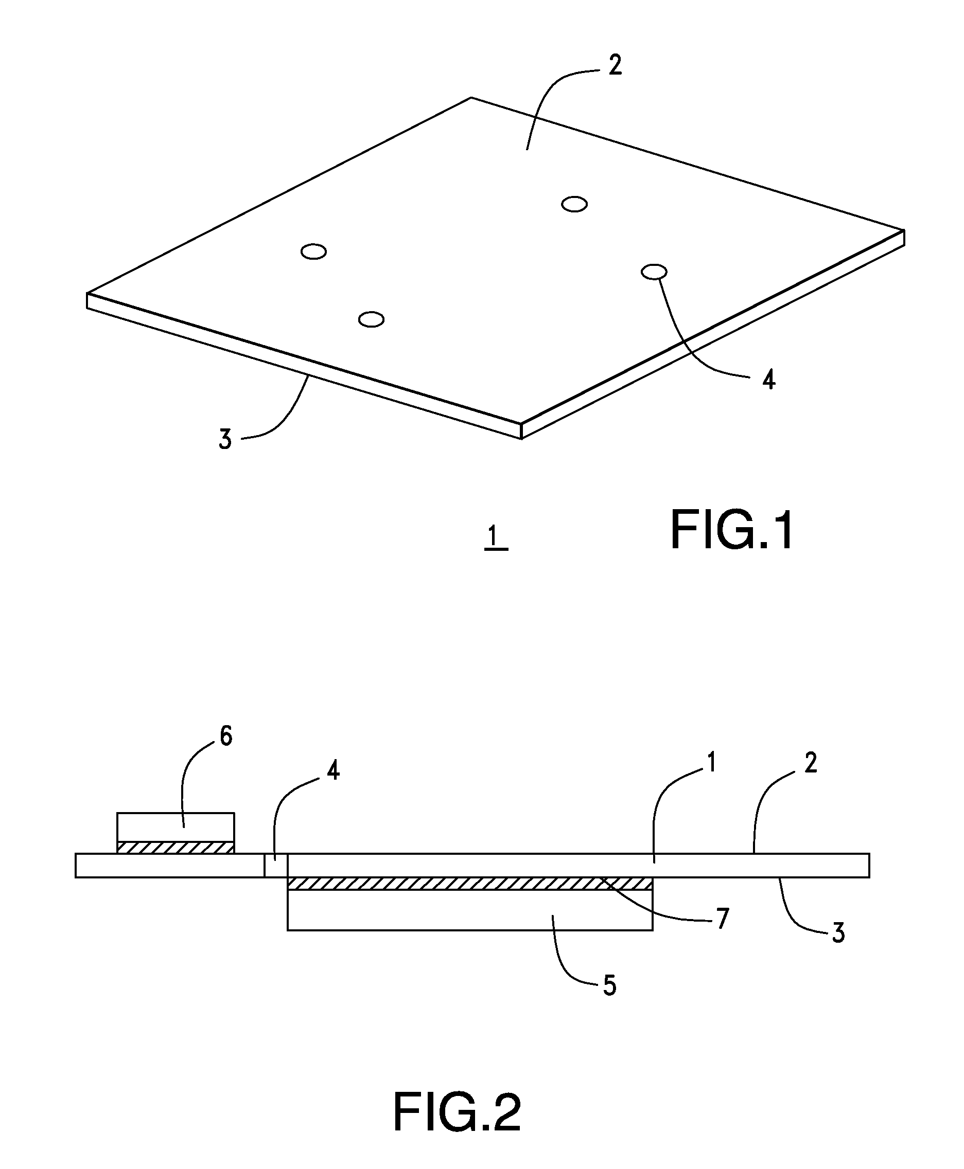
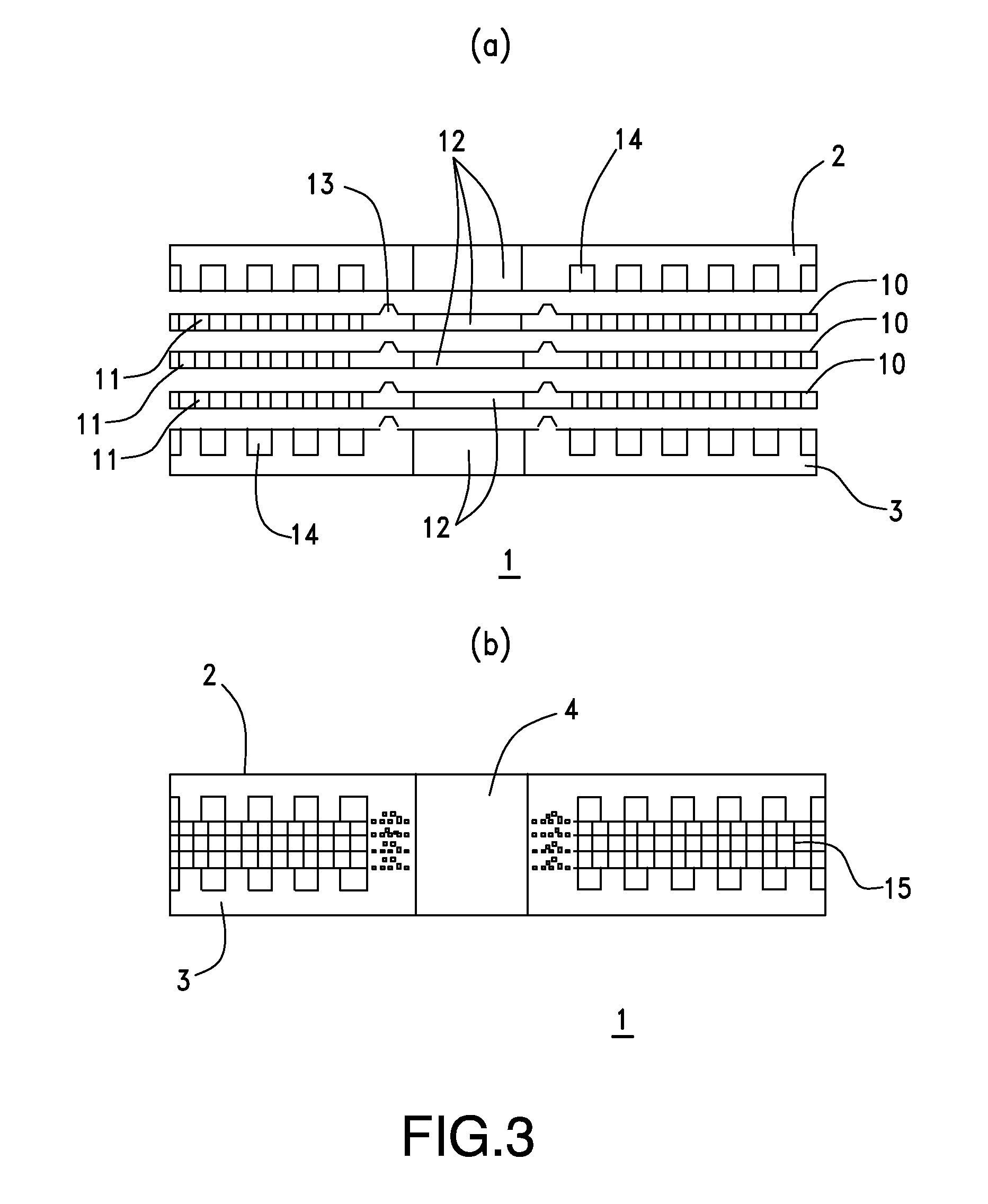
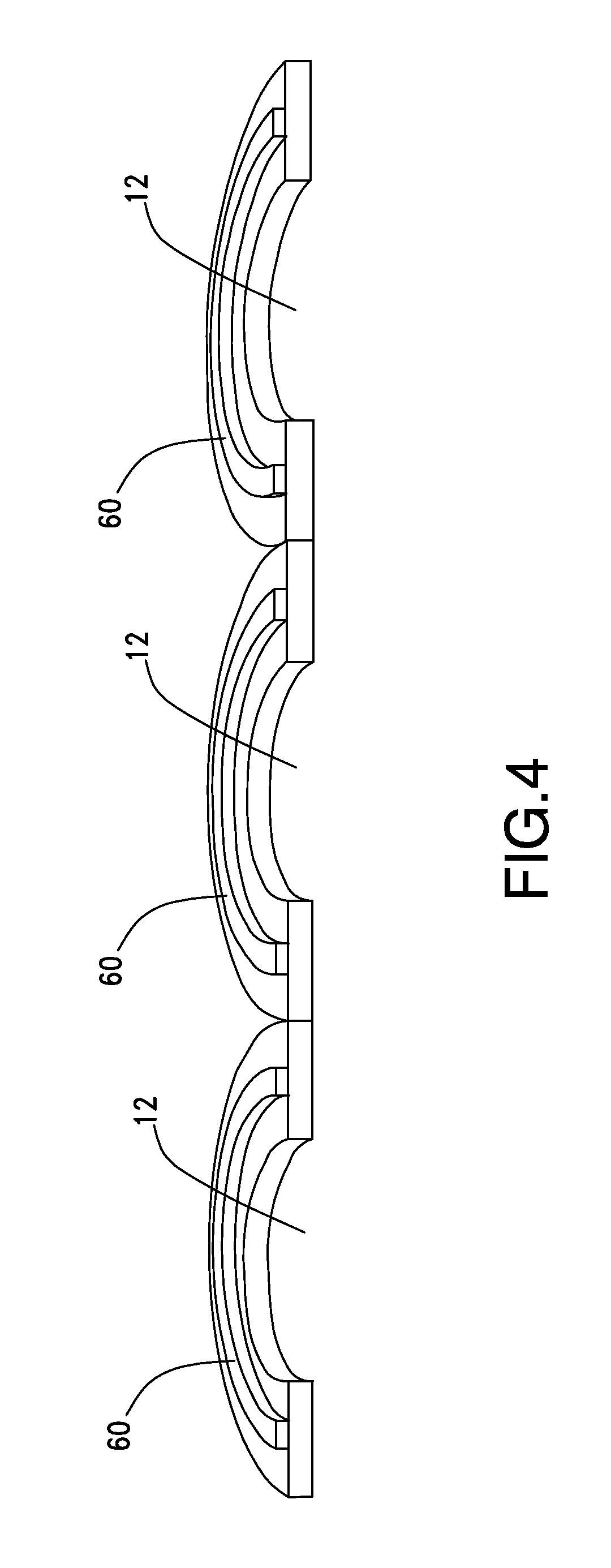
[0039]As used herein, the term “heat pipe” refers to a member, a part, an instrument or a device that can achieve the function of cooling a...


PUM

PropertyMeasurementUnit
thicknessaaaaaaaaaa
thicknessaaaaaaaaaa
areaaaaaaaaaaa

Abstract

A heat pipe for cooling an exothermic body by the vaporization and condensation of an enclosed cooling medium is disclosed. The heat pipe comprises a flat plate-like upper plate, a flat plate-like lower plate opposed to the upper plate, and a plurality of flat plate-like intermediate plates overlaid on each other between the upper plate and the lower plate and having internal through-holes. The internal through-holes formed in each of a plurality of the intermediate plates are adapted such that only part of each through-hole is overlapped on each other to form capillary tube paths, each having a cross-sectional area smaller than the cross-sectional area of the through-hole in the flat surface direction.

Description

REFERENCE To RELATED APPLICATIONS[0001]The Present Application is a United States National Phase Application, based on PCT Patent Application No. PCT / JP2009 / 0054415, filed with the Receiving Office of the Japanese Patent Office on 9 Mar. 2009. The PCT Patent Application (and, by extension, the Present Application) claims priority to Japanese Application No. 2008-080862, filed 26 Mar. 2008 with the Japanese Patent Office. The disclosures of both the PCT and the Japanese Applications are incorporated herein by reference in their entireties.BACKGROUND OF THE PRESENT APPLICATION[0002]The Present Application relates, generally, to a heat pipe for cooling exothermic bodies such as semiconductor integrated circuits, LED elements and power devices, a method for manufacturing the heat pipe and circuit boards with the heat pipe function.[0003]Electronic devices such as semiconductor integrated circuits, LED elements and power devices are used for electronic equipment, industrial equipment and...

Claims


Application Information

Patent Timeline
Patent Type & Authority Applications(United States)
IPC IPC(8): H05K7/20B21D53/02F28D15/04
CPCF28D15/0233F28D15/046H01L23/427H05K1/0204H05K1/0272H05K1/056H05K3/445H05K2201/064H01L2924/0002H01L2924/00Y10T29/4935
Inventor MIZUTA, KEITSURUTA, KATSUYAKOTANI, TOSHIAKIOHSAWA, KENJI
Owner FUCHIGAMI MICRO
Why Eureka
Try Eureka