Method for the dry dispersion of nanoparticles and the production of hierarchical structures and coatings

Active Publication Date: 2012-05-03
CONSEJO SUPERIOR DE INVESTIGACIONES CIENTIFICAS (CSIC)
View PDF5 Cites 2 Cited by
  • Summary
  • Abstract
  • Description
  • Claims
  • Application Information

AI Technical Summary

Benefits of technology

[0009]This invention proposes a low shear method for the dry dispersion of nanoparticles on other particles or substrates of varied morphology (circular, planar, in the form of thread) and nature (organic, inorganic and polymeric, etc.), which allows the production of a new class of materials in which particles are scattered over larger particles and even the formation of coatings on various substrates is achieved. This process is characterized by the absence of solvents during the same, i.e. it is a dry process that does not require high shear rates.

Problems solved by technology

The high specific surface of the nanoparticles causes them to agglomerate, thus dramatically reducing their effectiveness and modifying their properties with regard to the dispersed state.
In many cases, the solvents used are not environmentally friendly.

Method used


Image

  • Method for the dry dispersion of nanoparticles and the production of hierarchical structures and coatings
  • Method for the dry dispersion of nanoparticles and the production of hierarchical structures and coatings
  • Method for the dry dispersion of nanoparticles and the production of hierarchical structures and coatings

Examples


example 1

A Method for Obtaining Co304 Nanoparticles Dispersed on Al203 Support Particles

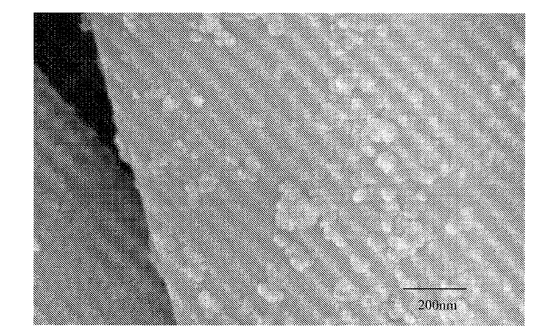
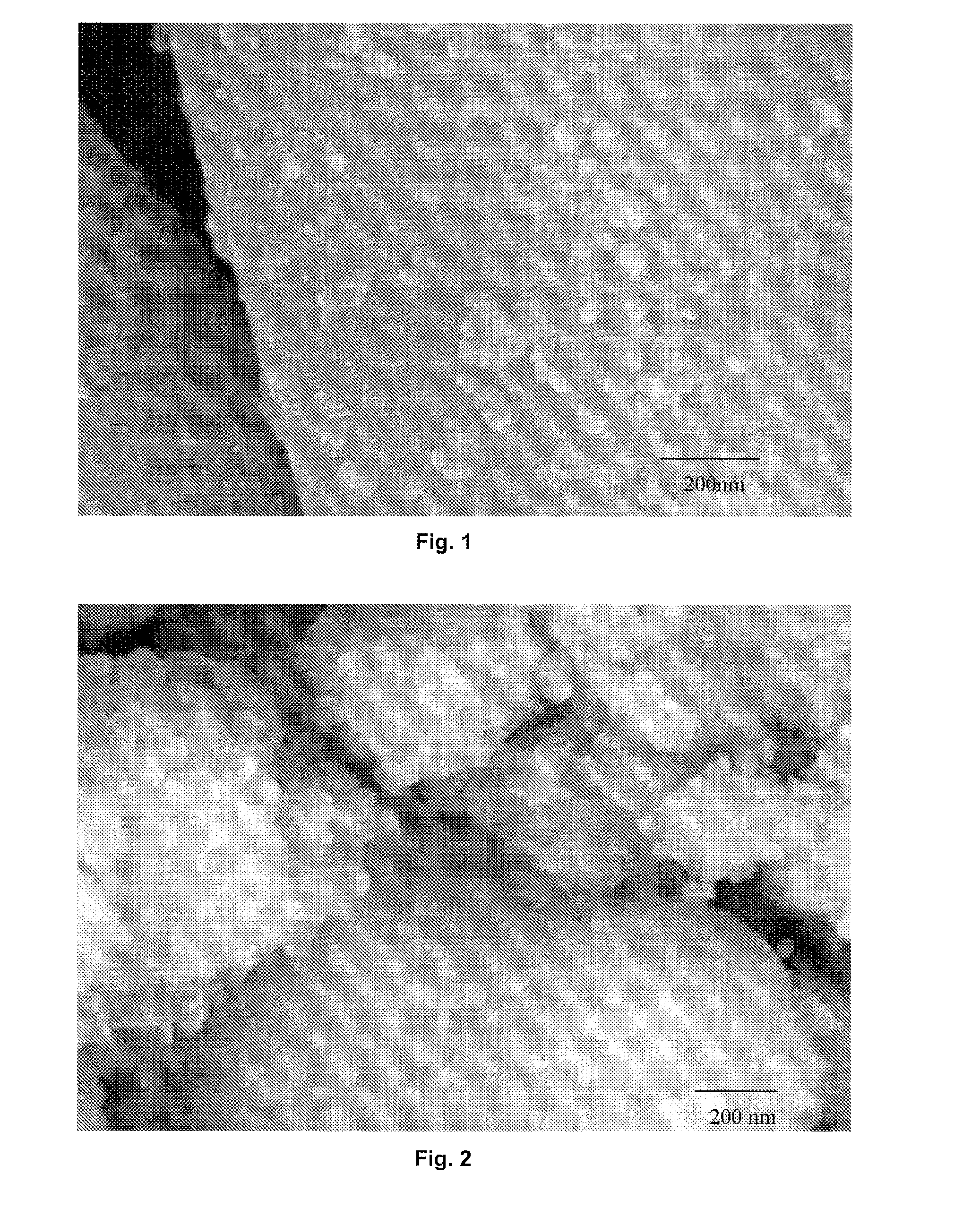
[0046]5 g of Al203 particles with an average particle size of −6 μm and 0.05 grams of Co304 nanoparticles with an average size below 50 nm were used. The two ceramic powders were added to a closed tubular nylon container, with a volume of 60 cm3 of a Turbula type shaker mixer, occupying ¼ of the available volume. The container was stirred at a speed of 30 rpm for 5 minutes. The container was emptied and the resulting mixture showed an effective dispersion Co304 nanoparticles on the Al203 support particles, as shown in FIG. 1. By modifying the percentage of nanoparticles from 0.03% by weight to 5% by weight, an effective dispersion was obtained according to the reflectance curve in FIG. 4. For higher weight percentages of nanoparticles in the mix, non-dispersed agglomerates are obtained along with the dispersed nanoparticles.

example 2

A Method for Obtaining Sepiolite Nanoparticles Dispersed on a Substrate of Glass Fibre in the Form of Thread

[0047]5 grams of fibre glass were used, having an average length of 3 mm and a diameter of 10 μm, and 5% by weight of sepiolite fibrillar particles with an average length of 1.5 μM and an average diameter of 40 nm. The two materials were added to a closed tubular nylon container, with a volume of 60 cm3 of Turbula type shaker mixer. The container was stirred at a speed of 60 rpm for 10 minutes. The container was emptied and the resulting mixture showed an effective dispersion of sepiolite nanoparticles on glass fibre yarns as shown in FIG. 10.

example 3

A Method for Obtaining NiO Nanoparticles Dispersed on a Monocrystalline Si Substrate with Native Oxide Layer

[0048]A flat monocrystalline Si substrate with a 2 cm2 surface area was fixed by means of adhesive tape on the inside of the lid of the closed container used in the Turbula type shaker mixer. 1 gram of NiO nanoparticles smaller than 20 nm is introduced into the container. The mixture was stirred at a speed of 42 rpm for 3 minutes. Once the substrate had been removed, excess nanoparticles deposited on the surface were removed using a compressed air pistol at 4 bar pressure. The thickness of the layer of dispersed NiO nanoparticles was 30 nm determined by ellipsometry.


PUM

PropertyMeasurementUnit
Percent by massaaaaaaaaaa
Thicknessaaaaaaaaaa
Sizeaaaaaaaaaa

Abstract

The invention relates to a method for the dispersion of synthetic or natural nanoparticles and nanocomposite materials and to the use thereof in different sectors including those of ceramics, coatings, polymers, construction, paints, catalysis, pharmaceuticals and powdered materials in general.

Description

[0001]The present invention relates to a process for the dispersion of synthetic or natural nanoparticles and nanocomposite materials and their applications in several sectors, most notably the sectors of ceramics, coatings, polymers, construction, paints, catalysis, pharmaceuticals and powdery materials in general.STATE OF THE ART[0002]The use of nanoparticles is growing dramatically in different industry areas. The unstoppable rise in applications in recent years is based on a growing availability of different types of nanoparticles of an oxidic or non-oxidic nature, with an organic or inorganic structure, and obtained in a synthetic or extractive way. Nanoparticles are usually used in combination with other compounds, whether nanoparticulate or not, and serve largely as a precursor of the so-called nanocomposites, which are composite-type materials in which one of the elements that comprises it has a nanoscale size, under 100 nm, in at least one of its dimensions. Materials with ...

Claims


Application Information

Patent Timeline
IPC IPC(8): A61K9/14B01J13/00C08L77/00B01J35/02B01F23/80B82Y5/00B82Y30/00
CPCB01J23/74B01J23/80B01J35/0013B01J37/04B82Y30/00C01P2002/82C01P2004/64C04B35/62826C04B35/62889C04B35/62892C04B2235/3217C04B2235/3284C04B2235/5436C09C1/407C09C3/04C09C3/063B01F13/0052Y10S977/902Y10S977/773Y10S977/906C01P2004/03B01F33/251B01J35/23B01J21/00C04B35/00D01F8/00B01F23/60B01F31/00
Inventor FERNANDEZLOZANO, JOSE FRANCISCOLORITE VILLALBA, ISRAELRUBIO MARCOS, FERNANDOROMERO FANEGO, JUAN JOSEGARCIA GARCIA-TUNON, MIGUEL NGELQUESADA MICHELENA, ADRIANMARTIN GONZALEZ, MARIA SOLEDADCOSTA KRAMER, JOSE LUIS
Owner CONSEJO SUPERIOR DE INVESTIGACIONES CIENTIFICAS (CSIC)
Why Eureka
Try Eureka