Control method for cooling a turbine stage in a gas turbine

a control method and turbine technology, applied in the direction of engines, mechanical equipment, machines/engines, etc., can solve the problems of not taking into account the power output or turbine, reducing combustion airflow, and not accurately adjusting cooling air consumption, so as to prevent overheating, prolong working life, and increase reliability

Inactive Publication Date: 2012-05-10
ANSALDO ENERGIA SPA
View PDF11 Cites 12 Cited by
  • Summary
  • Abstract
  • Description
  • Claims
  • Application Information

AI Technical Summary

Benefits of technology

[0005]It is an object of the present invention to provide a control method for cooling a turbine stage in a gas turbine, designed to provide a simple, low-cost solution to the above drawbacks, and, in particular, to optimize cooling airflow in different operating conditions.
[0007]The control method according to the invention provides for optimizing cooling air consumption, improving efficiency and increasing power at high loads, and reducing emissions at low loads.
[0010]Finally, unlike Patent EP1084327, the strategy devised provides for controlling the operating temperature of turbine components such as the rotor and stator blades, and, by preventing overheating, ensures greater reliability and a longer working life of thermally stressed parts (such as the stator and rotor blades).

Problems solved by technology

This control strategy has the drawback of apparently not taking into account the power output or turbine load, and of failing to accurately adjust cooling air consumption.
For example, in the event of excessive cooling air consumption, at high loads the reduction in combustion airflow could increase temperature in the combustion chamber and therefore nitric oxide emissions.
Conversely, an excessive reduction in cooling air consumption at low loads could cause a temperature drop in the combustion chamber and therefore an increase in carbon monoxide emissions and particulate.

Method used


Image

  • Control method for cooling a turbine stage in a gas turbine
  • Control method for cooling a turbine stage in a gas turbine
  • Control method for cooling a turbine stage in a gas turbine

Examples


Embodiment Construction

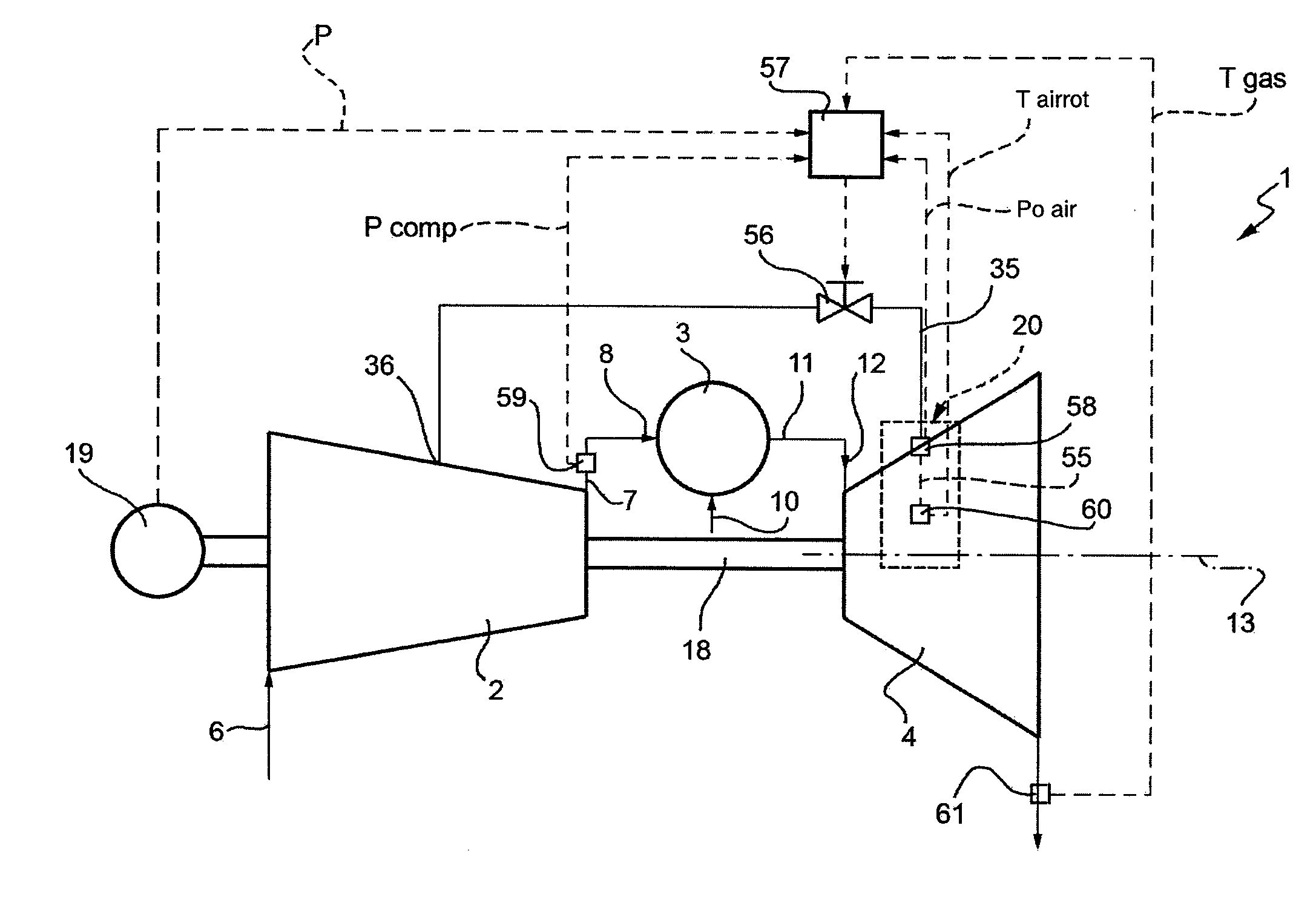
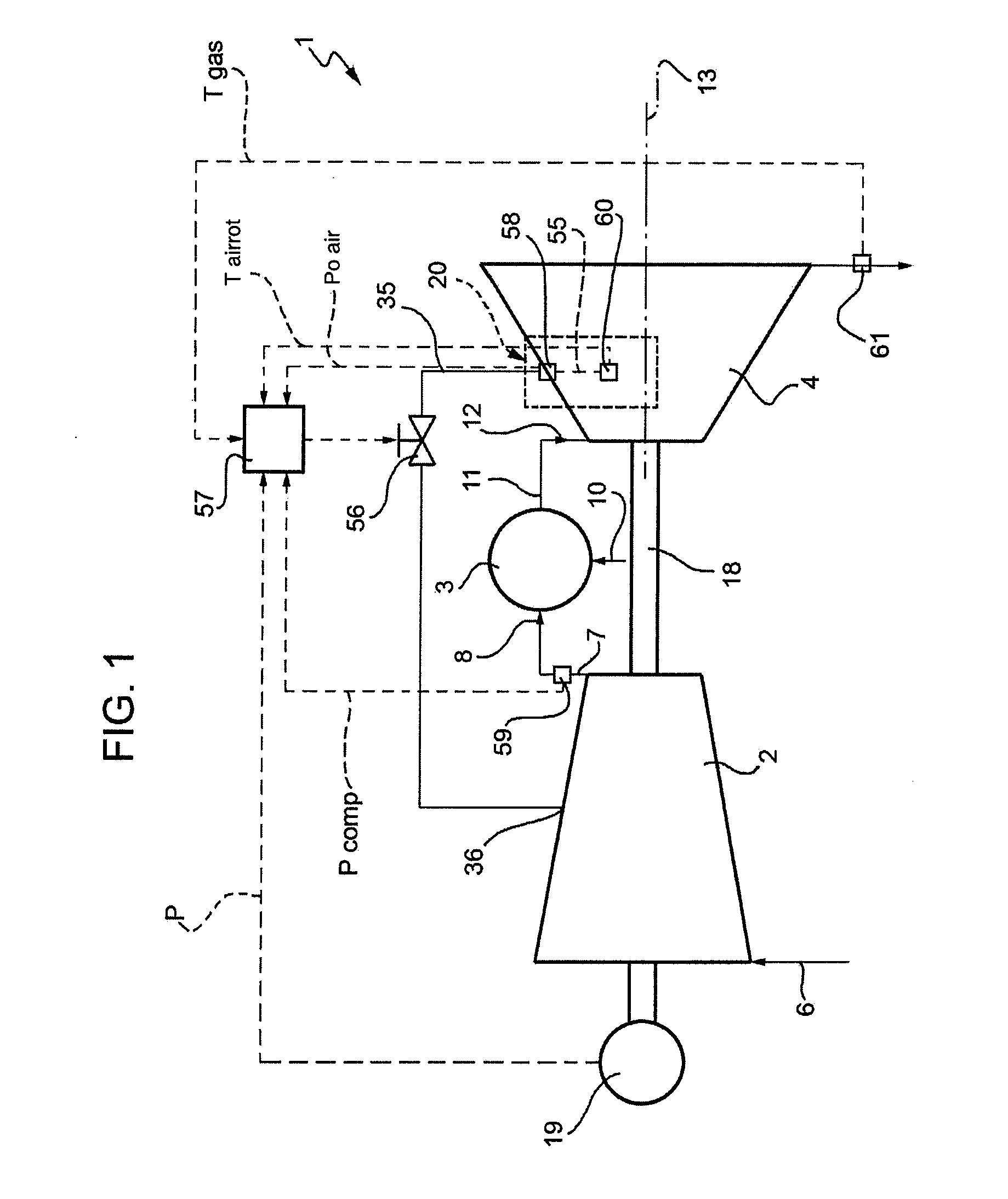
[0016]Number 1 in FIG. 1 indicates a gas turbine (shown schematically) comprising a compressor 2, a burner 3, and a high-pressure turbine 4. Compressor 2 is fed with air through an inlet 6, and has an outlet 7 connected to the inlet 8 of burner 3, which is fueled by a line 10 and has an outlet 11 connected to the inlet 12 of turbine 4.

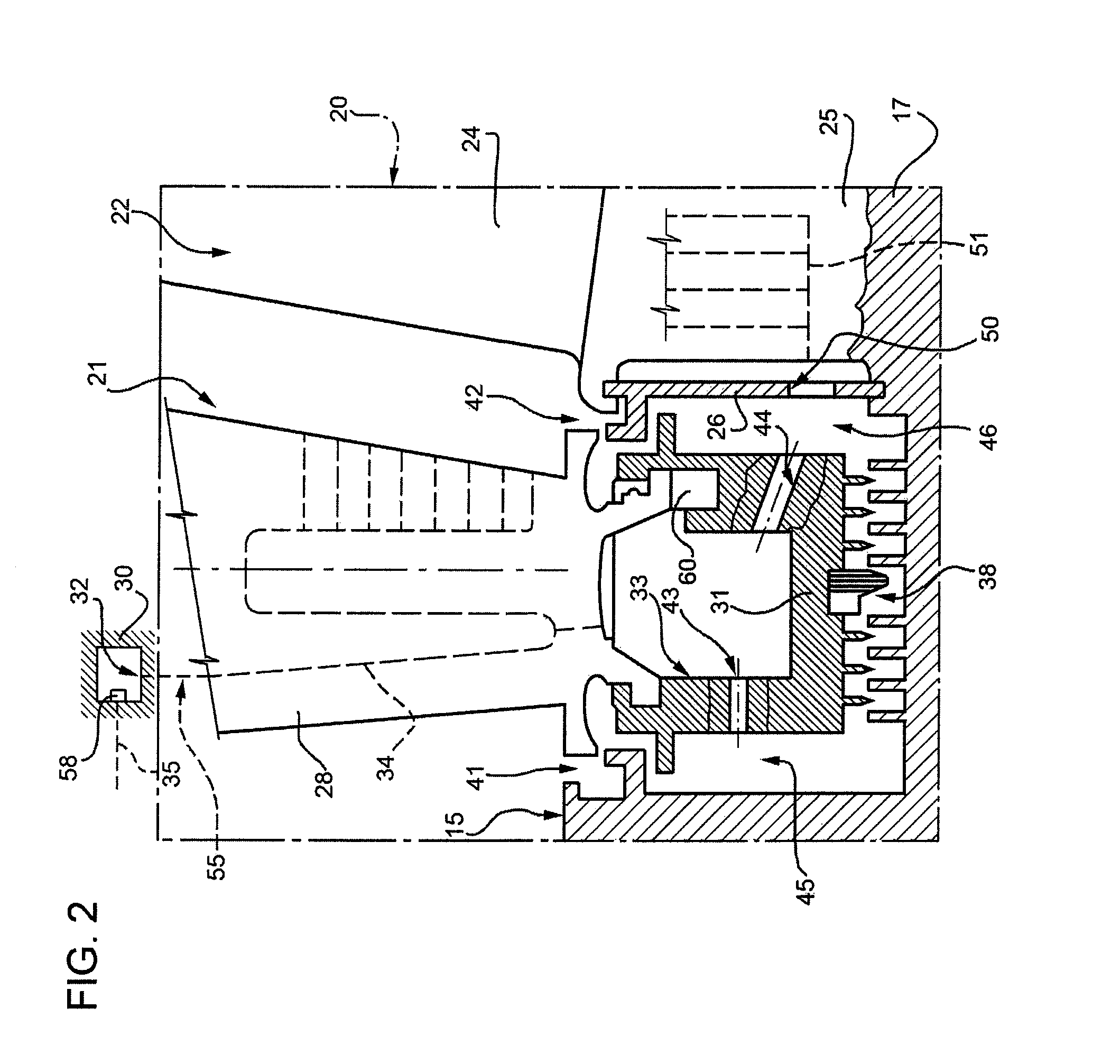
[0017]With reference to FIG. 2, turbine 4 extends along an axis 13 (FIG. 1), and has an annular conduit 15 (shown partly) defined externally by a fixed annular structure, and internally by a hub 17 fitted to a rotary shaft 18 (FIG. 1) powering compressor 2 and normally also an alternator 19. The burnt gases in conduit 15 encounter a number of successive stages 20, only one of which is shown partly. For the sake of simplicity, the following description refers to this one stage 20, it being understood that the same also applies to all the others.

[0018]Stage 20 comprises a stator 21 and a rotor 22. Rotor 22 comprises an array of blades 24, the inner radia...


PUM


Abstract

A control method for cooling a turbine stage of a gas turbine, whereby cooling air is bled from combustion air flowing in a compressor of the gas turbine, and is fed to a cooling circuit staring from a stator of the turbine stage; and cooling airflow is adjusted as a function of the pressure at the inlet of the cooling circuit, and as a function of the combustion air pressure at the exhaust of the compressor; more specifically, there is a feedback control setting a setpoint, which is predetermined as a function of the power output of the turbine to reduce contaminating emissions.

Description

[0001]The present invention relates to a control method for cooling a turbine stage in a gas turbine, as defined in the preamble of Claim 1.BACKGROUND OF THE INVENTION[0002]EP1084327 describes a control method for feeding cooling air from a compressor to the stator and rotor blades of a given turbine stage. The cooling air flows through the stator blades and the stator inner ring into the rotor of the same stage, and finally through the rotor blades. A valve for regulating cooling airflow upstream from the stator is operated by a control unit, which operates on the basis of a feedback signal from a pressure sensor at the valve outlet, and, in the control method described, adjusts cooling airflow to maintain a predetermined pressure signal from the sensor.[0003]This control strategy has the drawback of apparently not taking into account the power output or turbine load, and of failing to accurately adjust cooling air consumption. For example, in the event of excessive cooling air con...

Claims


Application Information

Patent Timeline
IPC IPC(8): F02C6/08
CPCF02C7/18F02C9/18F05D2270/08F05D2260/205F05D2270/3011F05D2270/3013F05D2270/303F05D2270/082
Inventor BOZZI, LUCAMANTERO, MARCOBONZANI, FEDERICO
Owner ANSALDO ENERGIA SPA
Why Eureka
Try Eureka