Heating coil welding fitting

a welding fitting and heating coil technology, applied in the direction of mechanical work/deformation, pipe connection arrangement, lamination, etc., can solve the problems of local overheating, increased labor intensity, and increased effort required for connecting individual pipeline components, so as to reduce the requisite energy and reduce the heat. the effect of tim

Inactive Publication Date: 2012-05-10
GEORG FISCHER ROHRLEITUNGSSYST
View PDF5 Cites 0 Cited by
  • Summary
  • Abstract
  • Description
  • Claims
  • Application Information

AI Technical Summary

Benefits of technology

[0009]This object is achieved according to the invention in that the heating wire winding is wavy, preferably sinusoidal, and the fitting can be deformed as a result. As a result of the wavy course, the heating coil welding fitting can be elastically deformed and the sleeve or the nipple can be compressed as a result. This enables the electric welding sleeve to be compressed by a clamping tool, said electric welding sleeve, for installation reasons, having a larger inside diameter than the outside diameter of the pipe to be inserted. One possibility for compressing an electric welding sleeve consists in contracting the sleeve by means of a clamping set placed around the circumference of the electric welding sleeve until the inside diameter of the sleeve and the outside diameter of the pipeline bear against one another and in subsequently welding them. Optimum heat transfer from the heating element or the heating coil welding sleeve or of the nipple to the pipeline is made possible by the two diameters bearing against one another. Thus the heating times are considerably shortened and the requisite energy can be reduced, which is finally reflected in savings in the assembly costs of the pipelines.

Problems solved by technology

The larger the conduit diameter of the pipelines to be connected, the greater is the effort required for connecting the individual pipeline components.
Furthermore, in the case of a large gap and a long heating time, there is the risk of a wire emerging, which can lead to local overheating and to the formation of fumes and odours.
The emergence of a wire means that, due to the heating of the wire, the wire expands, that is to say it becomes longer and takes up more space.
Since the linear expansion of the heating wire is now not distributed regularly but rather is concentrated at one location, the wire often emerges due to the increased space required by the wire.
In the prior art cited above, the electric welding sleeves permit no deformation at all, i.e. the electric welding sleeves cannot be constricted or compressed, and as a result the gap between electric welding sleeve and pipeline remains, which, at a corresponding gap width, can in turn result in poor heat transfer and thus in poor welding of the electric welding sleeve to the respective pipeline components.
The disadvantage of such a pipe joint part is that the tightness of a pipe joint is no longer provided for due to the wedge-shaped incisions, a factor which is decisive for a pipeline system.

Method used


Image

  • Heating coil welding fitting
  • Heating coil welding fitting
  • Heating coil welding fitting

Examples


Embodiment Construction

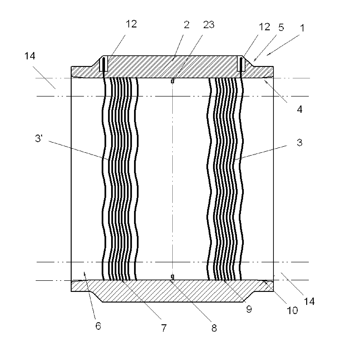
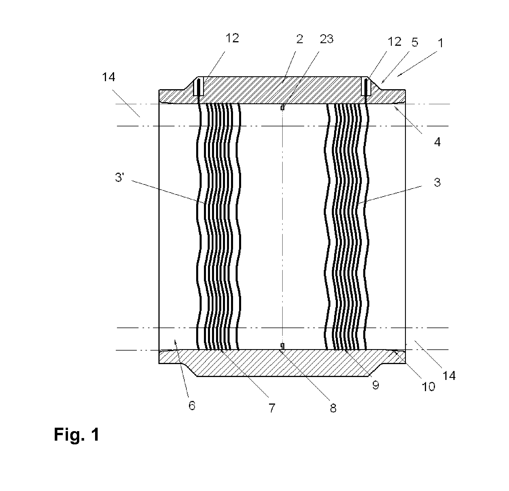
[0023]FIG. 1 shows a longitudinal section of a heating coil welding fitting 1 for connecting plastic pipeline components. The heating coil welding fitting 1 contains a sleeve 2 which is produced from a weldable thermoplastic. A respective pipeline section 14 is inserted on both sides into the inside diameter of the sleeve 2 in order to subsequently tightly weld the pipeline sections 14 to the heating coil welding fitting 1. The longitudinal axes of the two fitted-together pipeline sections 14 and the longitudinal axis of the heating coil welding fitting 1 are in alignment with one another. However, heating coil welding fittings 1 in which the connection pieces are arranged at a certain angle to one another, for example 60°, 90°, 120°, etc., are also conceivable. A further embodiment is a sleeve having different inside diameters on both sides, which enables two different pipeline cross sections to be fitted together. A combination of the two embodiments is likewise conceivable. Furth...


PUM

PropertyMeasurementUnit
diametersaaaaaaaaaa
sizeaaaaaaaaaa
angleaaaaaaaaaa

Abstract

A heating coil welding fitting comprising a cylindrical coupling body for welding pipelines made of thermoplastics or other weldable plastics, containing at least two heating wire windings, each with a plurality of turns which are at any desired distance from one another, and contacts for feeding the electric current, wherein the heating wire winding is wavy, preferably sinusoidal, and the coupling can be deformed as a result.

Description

BACKGROUND OF THE INVENTION[0001]The invention relates to heating coil welding fittings comprising a cylindrical coupling body for welding pipelines made of thermoplastics or other weldable plastics, containing at least two heating wire windings, each with a plurality of turns which are at any desired distance from one another, and contacts for feeding the electric current.[0002]For reasons of weight and corrosion, pipelines made of thermoplastics have been repeatedly used in pipeline construction mainly in recent years, specifically for the construction of pipeline networks for gas and water supply and for the delivery of air, waste water or even chemicals. The pipelines used are usually made of pressure-resistant plastic. To connect such pipelines, electric welding sleeves which have two heating coil welding zones are often used for reasons of efficiency. The larger the conduit diameter of the pipelines to be connected, the greater is the effort required for connecting the individ...

Claims


Application Information

Patent Timeline
Patent Type & Authority Applications(United States)
IPC IPC(8): B32B37/06
CPCB29C65/3432B29C65/3468B29C66/1222B29C66/1224B29C66/221B29C65/3476B29C66/3472B29C66/5221B29C66/52292B29C66/73921F16L47/03B29C66/223
Inventor WERMELINGER, JOERG
Owner GEORG FISCHER ROHRLEITUNGSSYST
Why Eureka
Try Eureka