

Tunable filter, tunable duplexer and mobile communication terminal using the same
- Summary
- Abstract
- Description
- Claims
- Application Information
AI Technical Summary
Benefits of technology
Problems solved by technology
Method used
Image

Examples
embodiment 1
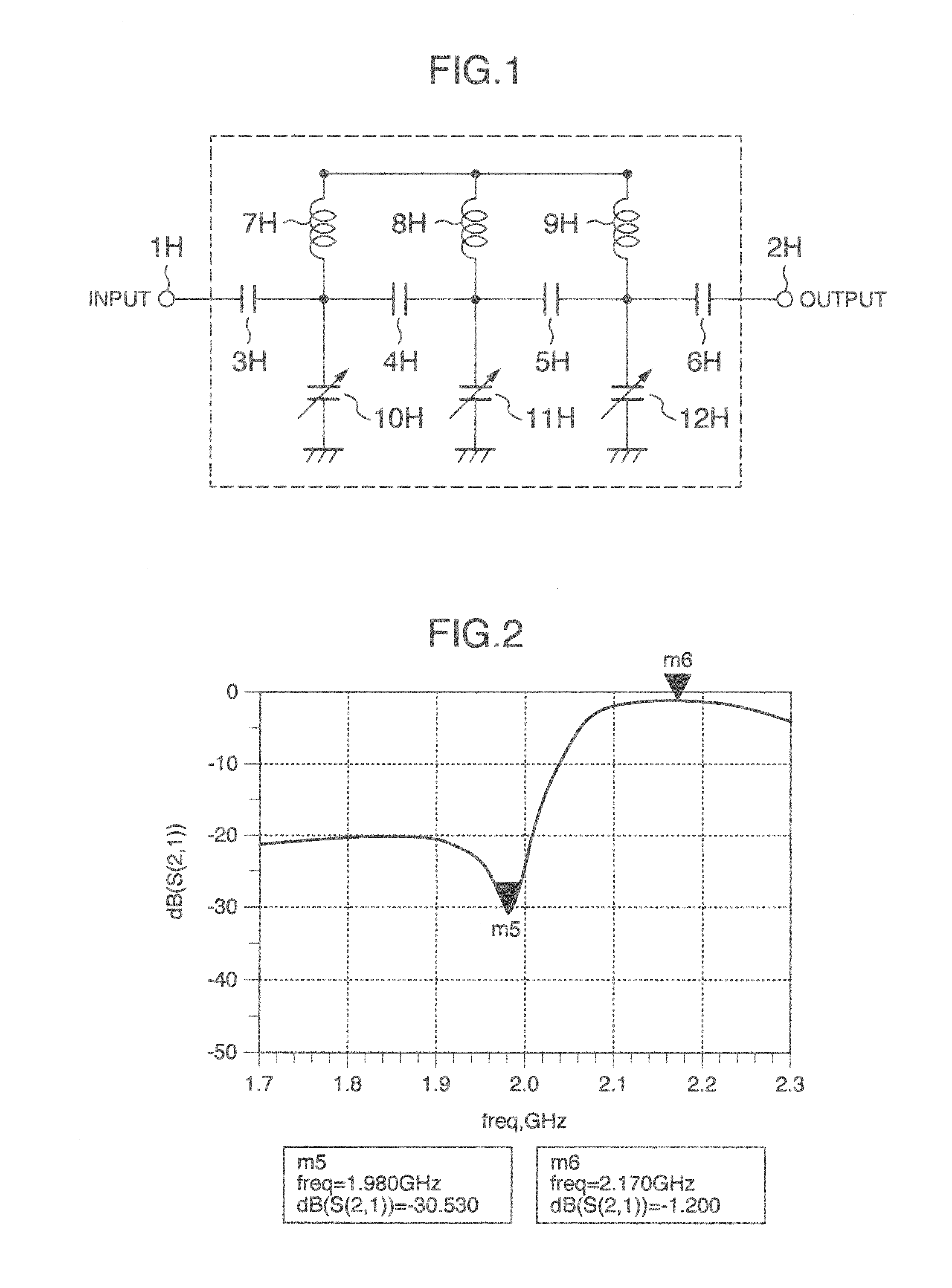
[0027]FIG. 1 is a circuitry showing an example configuration of a tunable filter tuned to relatively high frequencies in the first embodiment. This tunable filter is obtained as a pass-through characteristic in a direction from an input terminal 1H to an output terminal 2H, or in a reverse direction.
[0028]The tunable filter has a first fixed capacitor 3H connected between an input terminal 1H and a connecting point of a first pair of a variable capacitor 10H and a fixed coil 7H; a second fixed capacitor 4H connected between the connecting point of the first pair of the variable capacitor 10H and the fixed coil 7H and a connecting point of a second pair of a variable capacitor 11H and a fixed coil 8H and; a third fixed capacitor 5H connected between the connecting point of the second pair of the variable capacitor 11H and the fixed coil 8H and a connecting point of a third pair of a variable capacitor 12H and a fixed coil 9H; and a fourth fixed capacitor 6H connected between the conn...
embodiment 2
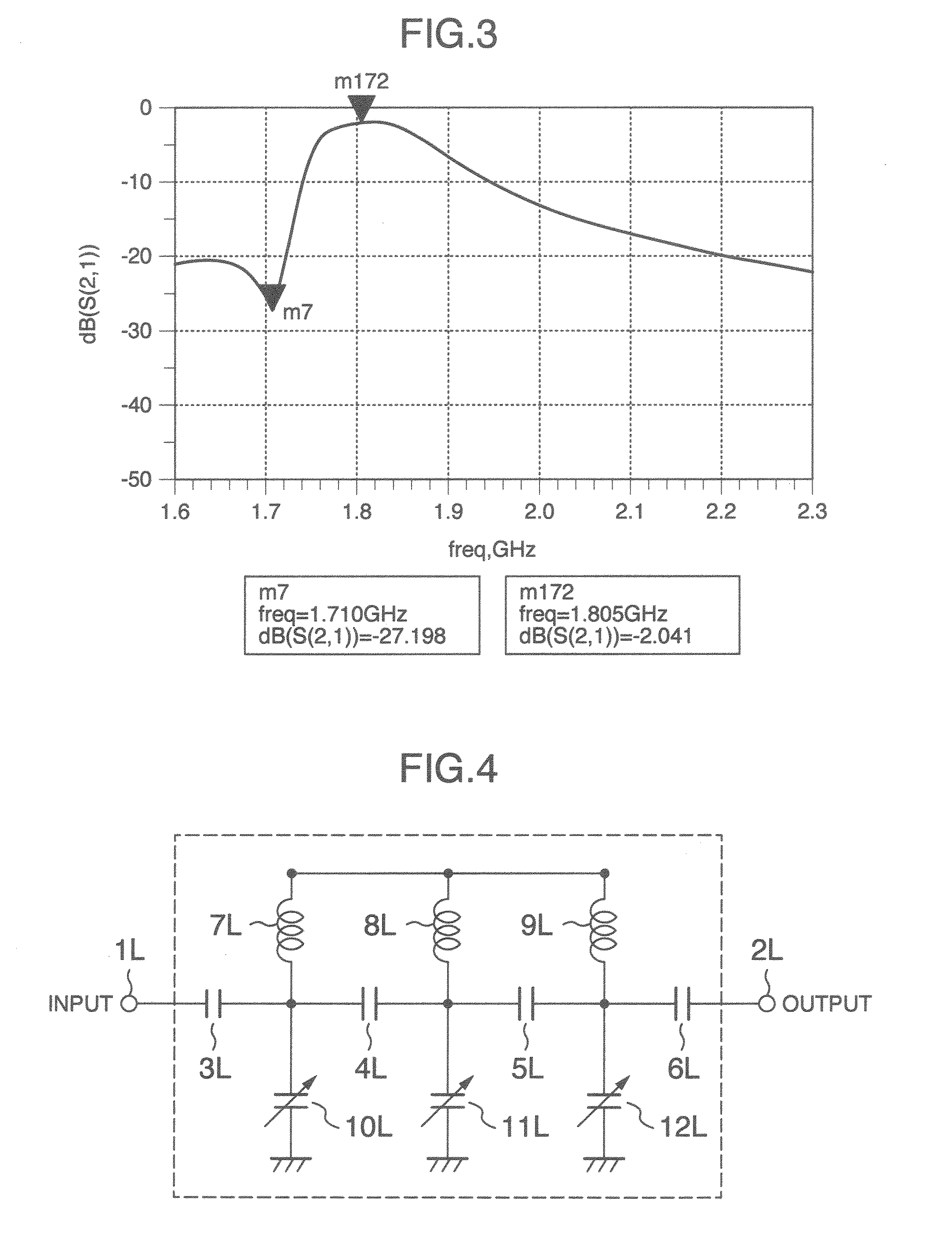
[0034]FIG. 4 is a circuitry showing a configuration of a tunable filter tuned to relatively low frequencies in a second embodiment. This tunable filter is obtained as a pass-through characteristics in a direction from an input terminal 1L to an output terminal 2L, or in a reverse direction.
[0035]A first fixed capacitor 3L is connected between the input terminal 1L and a connecting point of a first pair of a variable capacitor 10L and a fixed coil 7L; a second fixed capacitor 4L is connected between the connecting point of the first pair of the variable capacitor 10L and the fixed coil 7L and a connecting point of a second pair of a variable capacitor 11L and a fixed coil 8L; a third fixed capacitor 5L is connected between the connecting point of the second pair of the variable capacitor 11L and the fixed coil 8L and a connecting point of a third pair of a variable capacitor 12L and a fixed coil 9L; and a fourth fixed capacitor 6L is connected between the connecting point of the thir...
embodiment 3
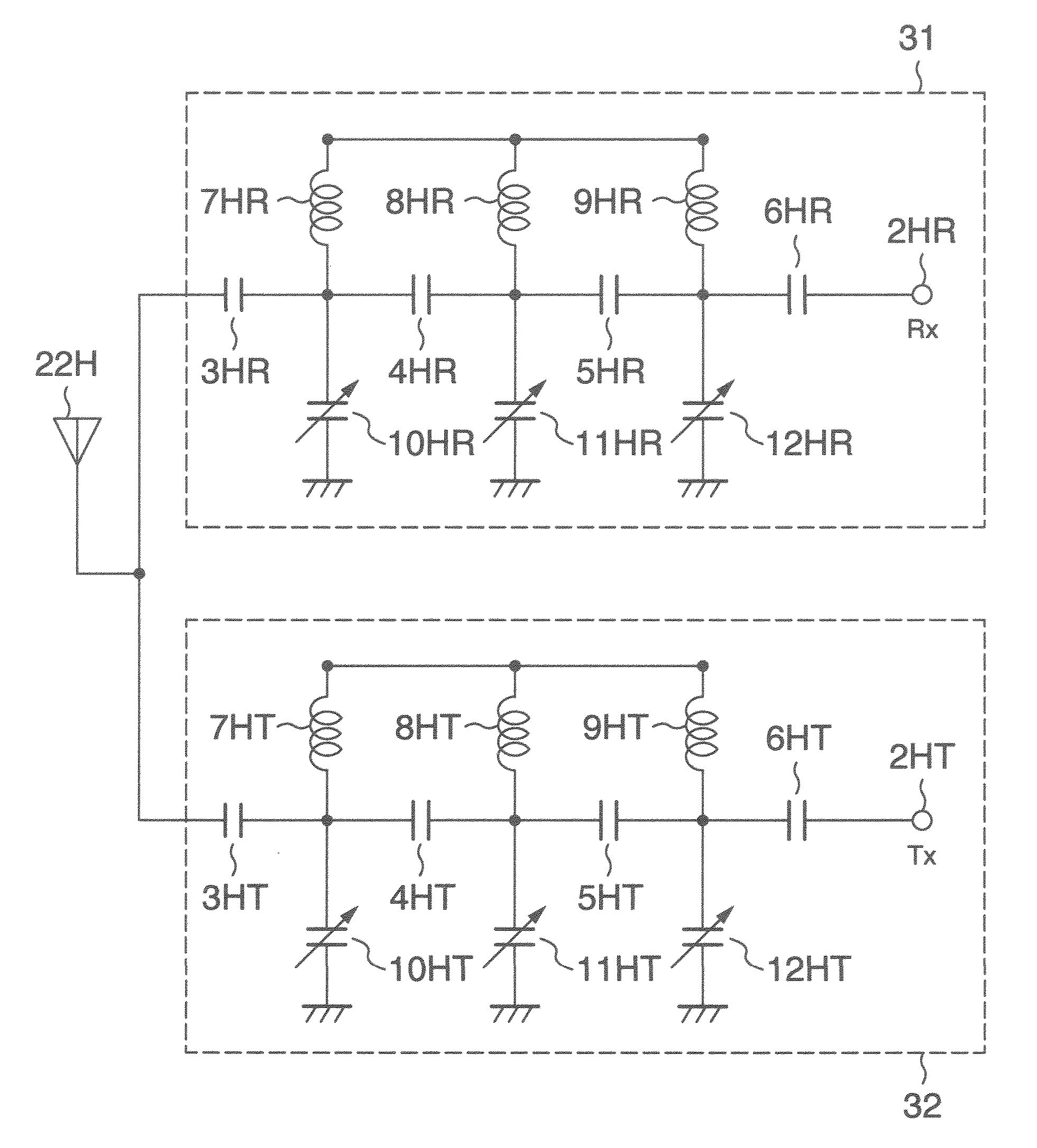
[0041]FIG. 7 shows a circuitry of a tunable filter module of the third embodiment. In this embodiment, a high-band tunable filter 27 uses the tunable filter of the first embodiment and a low-band tunable filter 28 the tunable filter of the second embodiment. An input terminal 1H of the high-band tunable filter 27 and an input terminal 1L of the low-band tunable filter 28 are connected to an antenna 21 through a SPDT (Single Pole Dual Throw) switch 20. That is, the SPDT switch 20 selects between the high-band tunable filter 27 and the low-band tunable filter 28 for connection to the antenna 21. The SPDT switch is formed of CMOS, SOS (Silicon on Sapphire) or GaAs switch. The tunable filter module of this configuration can be used as a diversity receiver circuit that covers almost all bands used in communication systems, such as WCDMA and LTE.
PUM
 Abstract
Description
Claims
Application Information