
Light guide apparatus

a technology of light guide and guide rod, which is applied in the direction of lighting and heating apparatus, instruments, electromagnetic radiation sensing, etc., can solve problems such as visible artefacts, and achieve the effect of larger clear viewing cone and strong light intensity

Inactive Publication Date: 2012-05-10
KONINKLIJKE PHILIPS ELECTRONICS NV
View PDF4 Cites 57 Cited by
  • Summary
  • Abstract
  • Description
  • Claims
  • Application Information

AI Technical Summary

Benefits of technology

[0010]According to an embodiment of the present invention, the light guide plate has two cladding layers covering respectively said first and second surface of the light guide plate and the index of either of the cladding layers is lower than the index of said light guide plate. By using the cladding layers, the light guide plate is scratch-resistant. Alternatively, in the case of a cladding configuration, the light guide apparatus further comprises a tapered collimator between the light source and the light guide plate for preventing the light from entering the cladding layers directly.
[0012]Alternatively, the light guide apparatus further comprises a second light source, coupled to a second side, opposite to the first side, of the light guide plate to achieve a much stronger diffraction light intensity.
[0014]By using two diffraction gratings, the light guide apparatus extracts a much stronger light intensity. By using two diffraction gratings with different pitches, the light guide apparatus achieves a larger clear viewing cone.

Problems solved by technology

However, the micro-structures in FIG. 1 have a certain size, for instance the spacing is 0.1 mm, which under certain circumstances results in visible artefacts.

Method used


Image

  • Light guide apparatus
  • Light guide apparatus
  • Light guide apparatus

Examples


Embodiment Construction

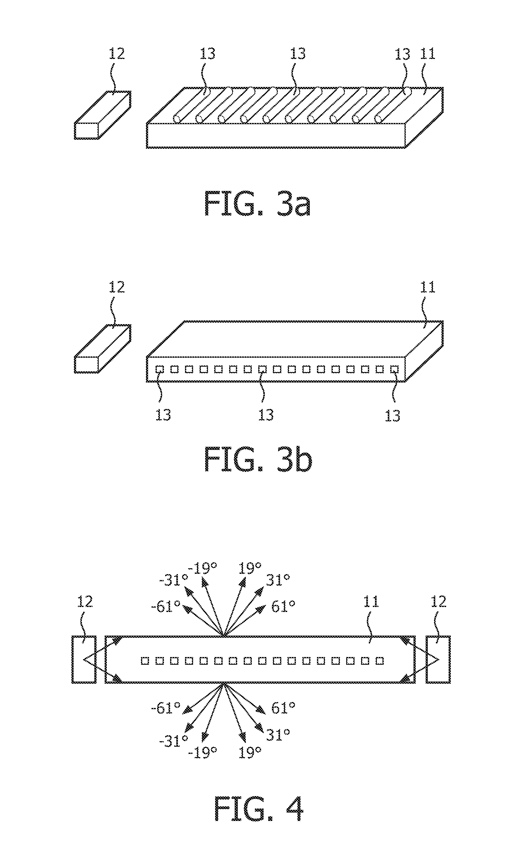
[0041]Referring to FIG. 3, FIG. 3 shows a light guide apparatus according to an embodiment of the present invention. The light guide apparatus in FIG. 3 includes a light guide plate 11 and a first light source 12. The light guide plate 11 has a first diffraction grating 13 on its first surface. The first light source 12 is coupled to a first side of the light guide plate 11. The first light source 12 includes a single LED, OLED, CCFL or EL or a plurality thereof. The light guide plate 11 can be made of polycarbonate (PC) or polymethylmethacrylate or PolyStyrene (PS) or Cyclic Olefin Copolymer (COC) etc.

[0042]In a variant embodiment of FIG. 3, the first diffraction grating 13 can also be located inside the light guide plate 11, as shown in FIG. 4.

[0043]Alternatively, the light guide apparatus further comprises a second light source 12, coupled to a second side, opposite to the first side, of the light guide plate 11, as shown in FIG. 5.

[0044]In FIG. 5, light is injected into the ligh...


PUM


Abstract

The present invention aims to provide a light guide apparatus based on diffraction gratings. The apparatus comprises a light guide plate (11) comprising a first diffraction grating (13) located on a first surface of or inside the light guide plate (11); a first light source (12), coupled to a first side of the light guide plate (11); wherein the first diffraction grating (11) is configured to extract the light generated by the first light source (12) from the first surface of the light guide plate (11). Since the first diffraction grating (13) is invisibly small, users hardly notice any change of the light guide (11). When the light guide apparatus of the present invention is used as a book reader, the dark area produced when lifting the book reader in a direction away from the objects to be read is smaller than that of existing light guide apparatus based on microstructures, since the light exit angle is relatively small when using a diffraction grating.

Description

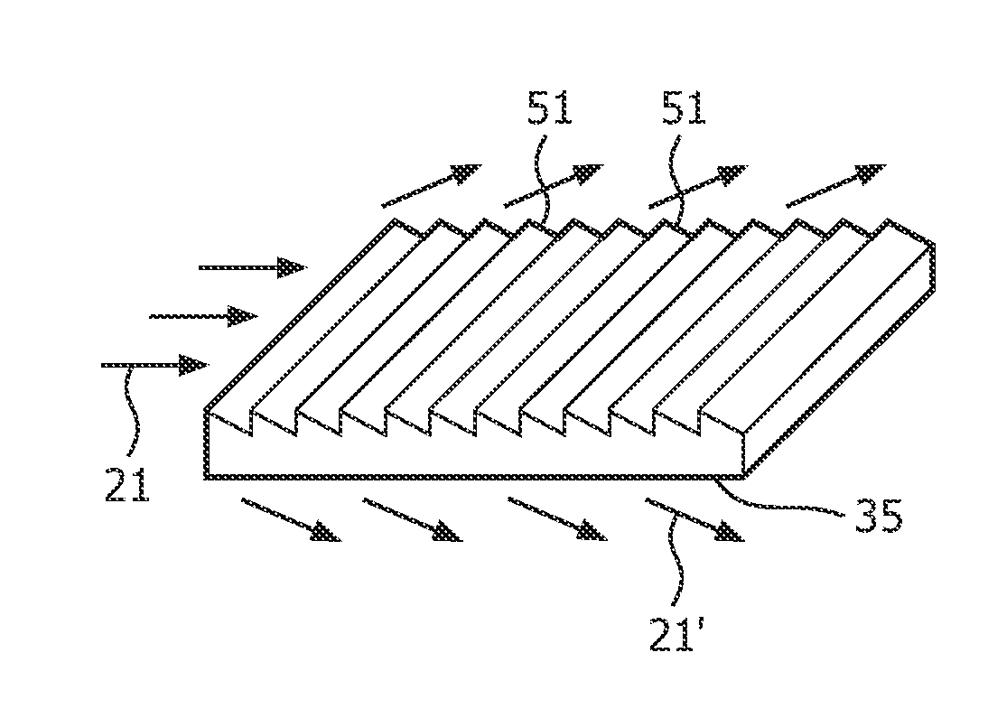
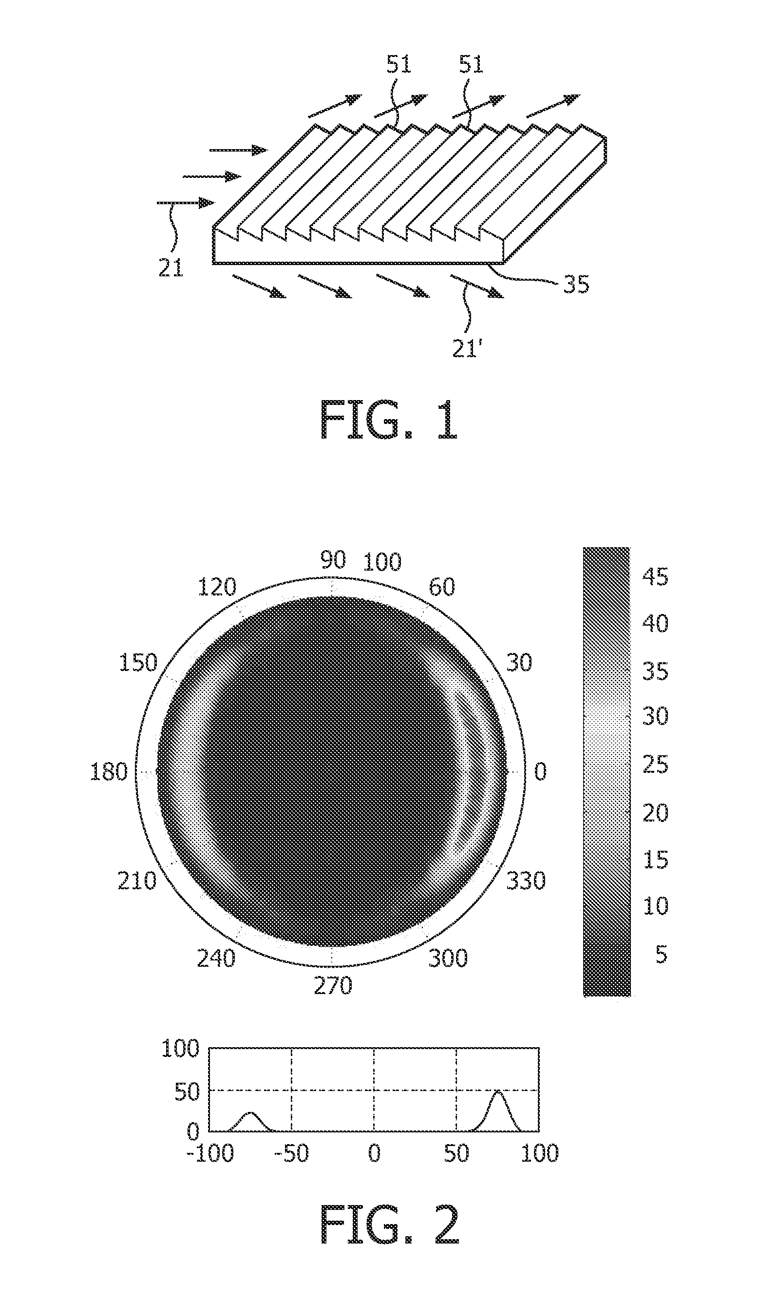
FIELD OF THE INVENTION[0001]The present invention relates to light guide apparatus, particularly to light guide apparatus used for book readers.BACKGROUND OF THE INVENTION[0002]A previous Philips patent application publication, international publication number: WO2008 / 087593, entitled “ILLUMINATION DEVICE”, filed on Jan. 16, 2008, proposed a book reader based on a light guide 35 having optical microstructures 51 that cause the guided light 21 to exit 21′ at a large angle with the surface normal, as shown in FIG. 1. From a plot of the angular distribution of the emitted light it can be seen that the exit angle is approximately 80° with respect to the normal to the bottom surface of the light guide 35, as illustrated in FIG. 2. In the second drawing of FIG. 2, the horizontal axis denotes the inclination angle, and the vertical axis denotes illumination intensity.[0003]However, the micro-structures in FIG. 1 have a certain size, for instance the spacing is 0.1 mm, which under certain c...

Claims


Application Information

Patent Timeline
Patent Type & Authority Applications(United States)
IPC IPC(8): F21V8/00G02B6/34
CPCG02B6/0025G02B6/0028G02B6/0038G02B6/0076G02B6/0063G02B6/0068G02B6/005G02B6/00G06K7/10
Inventor CORNELISSEN, HUGO JOHANBOER, DIRK KORNELIS GERHARDUSWEI, GONGMING
Owner KONINKLIJKE PHILIPS ELECTRONICS NV
Learn More