
Luminescent converter for a phosphor-enhanced light source

a technology converter, which is applied in the direction of discharge tube luminescnet screens, energy-saving lighting, sustainable buildings, etc., can solve the problems of reducing the efficiency of phosphor-enhanced light source, and the generation of long-wavelength light by two-step light conversion seems less efficient than in one step, so as to achieve the effect of improving efficiency

Active Publication Date: 2012-05-17
SIGNIFY HLDG BV
View PDF8 Cites 14 Cited by
  • Summary
  • Abstract
  • Description
  • Claims
  • Application Information

AI Technical Summary

Benefits of technology

[0009]It is an object of the invention to provide a luminescent converter having improved efficiency.

Problems solved by technology

However, the FWHM of the emission spectrum of the “Red”-contribution should be limited in order not to comprise too much infrared light as this only results in emission of non-usable infrared light which again reduces the efficiency of the phosphor enhanced light source.
Losses due to the conversion of the light by the luminescent material is a combination of the Stokes losses from each conversion and the losses due to the quantum efficiency of the luminescent material used for each conversion.
Generation of long-wavelength light by two-step light conversion seems less efficient than in one step because the efficiency is decreased by the product of the quantum efficiencies of each of the individual luminescent materials.

Method used


Image

  • Luminescent converter for a phosphor-enhanced light source
  • Luminescent converter for a phosphor-enhanced light source
  • Luminescent converter for a phosphor-enhanced light source

Examples


Embodiment Construction

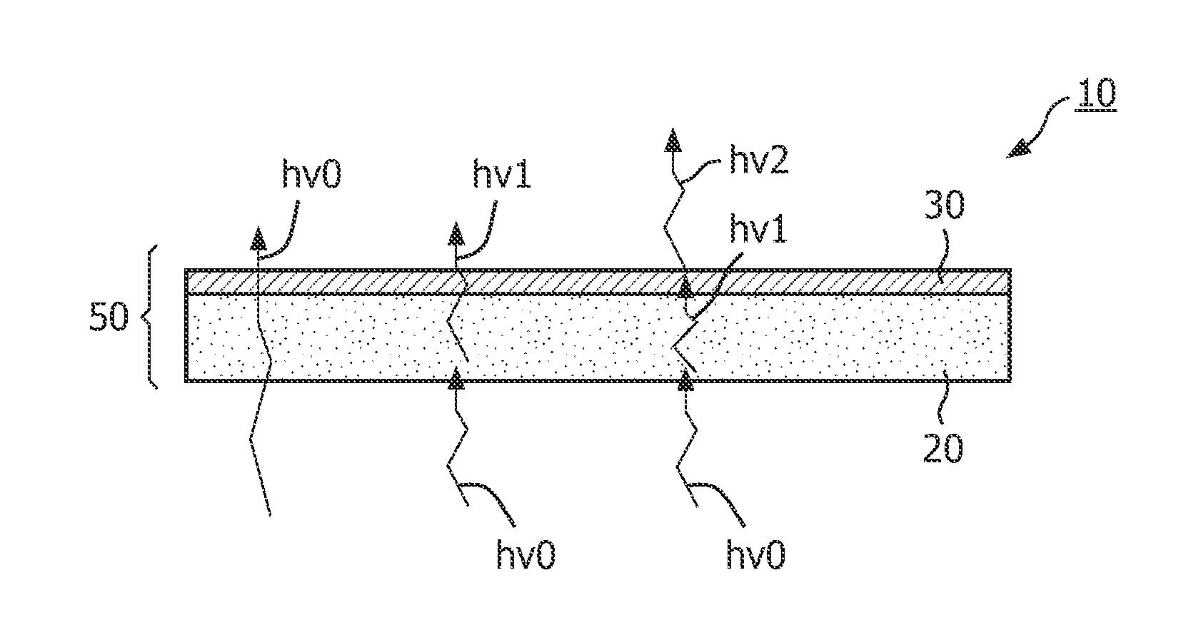
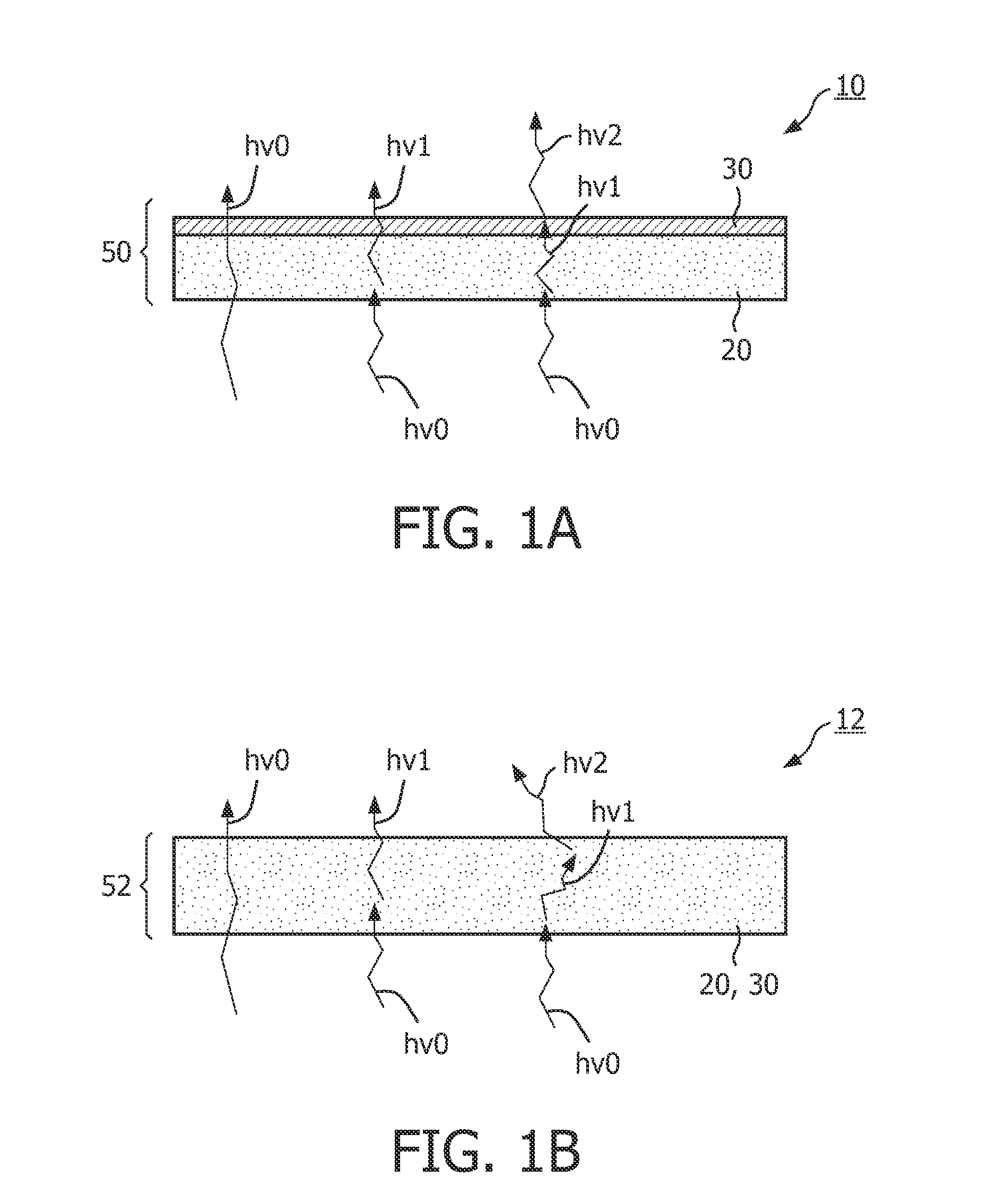
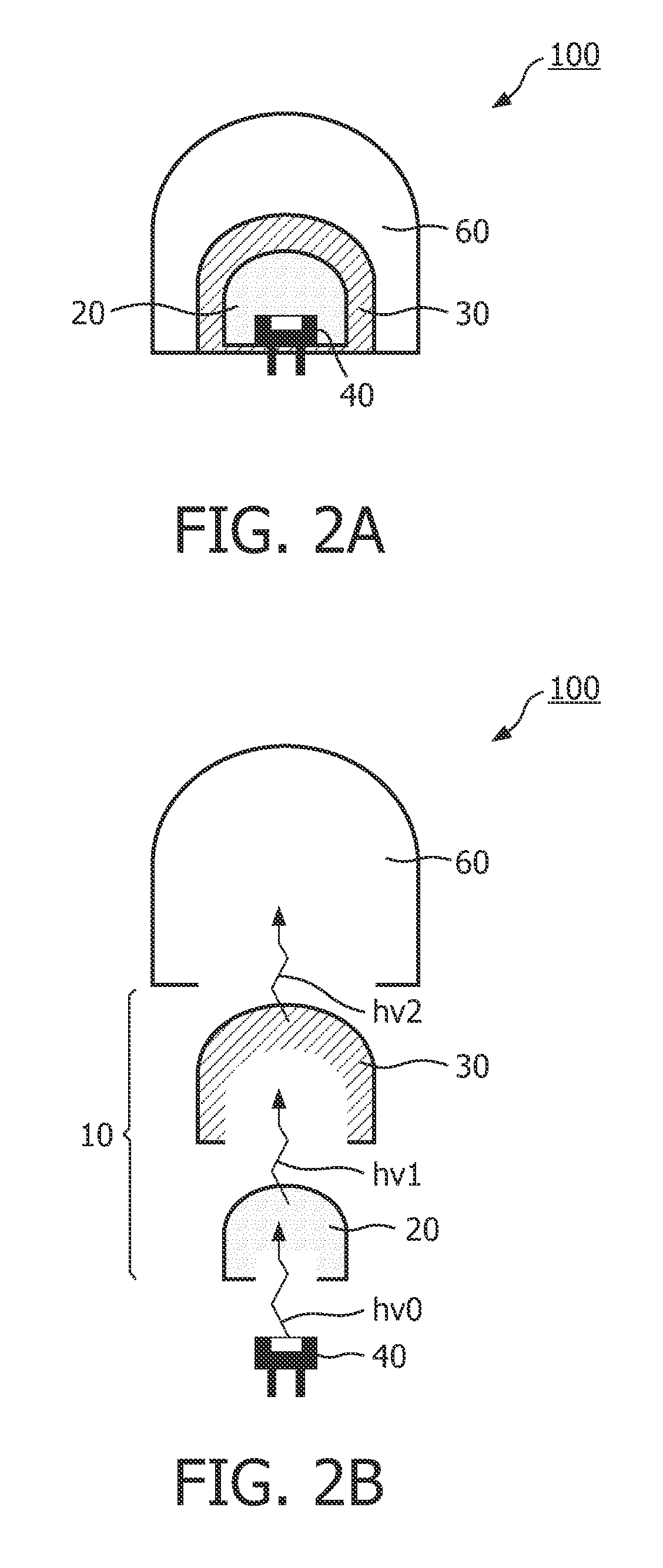
[0048]FIGS. 1A and 1B show a luminescent converter 10, 12 according to the invention. The luminescent converted 10, 12 is constituted of two different luminescent materials, a first luminescent material 20 and a second luminescent material 30 comprising an organic luminescent material 30. The first luminescent material 20 is configured for absorbing at least a part excitation light hv0 which impinges on the luminescent converter 10, 12. A part of the light absorbed by the first luminescent material 20 is subsequently converted into first emission light hv1 having a longer wavelength and emitted by the first luminescent material 20. The non-absorbed part of the excitation light hv0 may, for example, be transmitted through the luminescent converter 10, 12 and may contribute to the overall light emitted by the luminescent converter 10, 12 via mixing with the light emitted by the first luminescent material 20 and the second luminescent material 30. The second luminescent material 30 is ...


PUM


Abstract

The invention relates to a luminescent converter (10, 12) for a phosphor-enhanced light source (100, 102, 104). The luminescent converter comprises a first luminescent material (20) configured for absorbing at least a part of excitation light (hv0) emitted by a light emitter (40, 42) of the phosphor-enhanced light source, and for converting at least a part of the absorbed excitation light into first emission light (hv1) comprising a longer wavelength compared to the excitation light. The luminescent converter further comprising a second luminescent material (30) comprising organic luminescent material (30) and configured for absorbing at least a part of the first emission light emitted by the first luminescent material, and for converting at least a part of the absorbed first emission light into second emission light (hv2) having a longer wavelength compared to the first emission light.An effect of the luminescent converter according to the invention is that the two-step light conversion according to the invention generates a relatively small Stokes shift of the light emitted by the organic luminescent material. The inventors have found that by reducing the Stokes shift of the organic luminescent material, the width of the spectrum of the second emission light is limited to reduce an infrared part in the emission spectrum. As such, the efficiency is improved.

Description

FIELD OF THE INVENTION[0001]The invention relates to a luminescent converter for a phosphor-enhanced light source.[0002]The invention further relates to the phosphor-enhanced light source comprising a light emitter and the luminescent converter.BACKGROUND OF THE INVENTION[0003]Phosphor-enhanced light sources are known per se and are used for substantially all kinds of light sources. Phosphor-enhanced light sources comprise a light emitter and a luminescent material. The luminescent material is arranged for converting at least part of the light emitted by the light emitter into light of a longer wavelength.[0004]Well-known phosphor-enhanced light sources are, for example, mercury vapor discharge lamps in which the light is emitted from a discharge in which the presence of mercury vapor causes the discharge to emit ultraviolet radiation. At least a part of the ultraviolet radiation is absorbed by a luminescent material and converted into light of a longer wavelength which is subsequen...

Claims


Application Information

Patent Timeline
IPC IPC(8): H01J1/63H01J61/44H01J1/62
CPCC09K11/06C09K11/7774H01L33/504H01J61/48H01J61/44C09K11/77748Y02B20/00
Inventor STAATS, CORNELIA TITIAVAN DIJK, GERARDUS ARNOLDUS RITAWEGH, RENE THEODORUSVAN DE SPIJKER, WILLIBRORDUS HUBERTUS, MARTINUS, MARIAPEETERS, MARTINUS PETRUS JOSEPH
Owner SIGNIFY HLDG BV
Learn More