Trailing Edge Dimmer Compatibility With Dimmer High Resistance Prediction

a technology of high resistance and trailing edge, applied in the field of electronic devices, can solve the problems of transferring unnecessary current from the voltage supply, malfunctioning trailing edge dimmers, and inability to detect trailing edges, and achieve high resistan

Active Publication Date: 2012-05-17
SIGNIFY HLDG BV
View PDF2 Cites 71 Cited by
  • Summary
  • Abstract
  • Description
  • Claims
  • Application Information

AI Technical Summary

Benefits of technology

[0017]In one embodiment of the present invention, an apparatus includes a controller to provide compatibility between a lamp and a trailing edge dimmer. The controller is capable to predict an estimated occurrence of a high resistance state of the trailing edge dimmer. The high resistance state occurs when the trailing edge dimmer begins phase cutting an alternating current (AC) voltage signal. The controller is further capable to operate in a high current mode based on the estimated predicted occurrence of the high resistance state of the trailing edge dimmer. The controller is also capable to operate in a low impedance mode after the AC voltage signal reaches a low voltage threshold.

Problems solved by technology

One of the challenges is developing electronic light source based lamps that are compatible with existing infrastructure.
Failure to reach a zero-crossing can cause some trailing edge dimmers to malfunction.
The trailing edges of rectified input voltage VΦR—IN at times t1 and t4 are generally noisy and may contain other distortions.
However, because the rate of decay dVΦ—IN / dt is greater for electronic light sources, the low value of the trailing edge detection threshold also means that the trailing edge might not be detected before a zero crossing of the phase cut, rectified voltage VΦ—R for large phase angles.
Increasing the value of the trailing edge detection threshold can result in transferring an unnecessary amount of current from the voltage supply 104.

Method used


Image

  • Trailing Edge Dimmer Compatibility With Dimmer High Resistance Prediction
  • Trailing Edge Dimmer Compatibility With Dimmer High Resistance Prediction
  • Trailing Edge Dimmer Compatibility With Dimmer High Resistance Prediction

Examples


Embodiment Construction

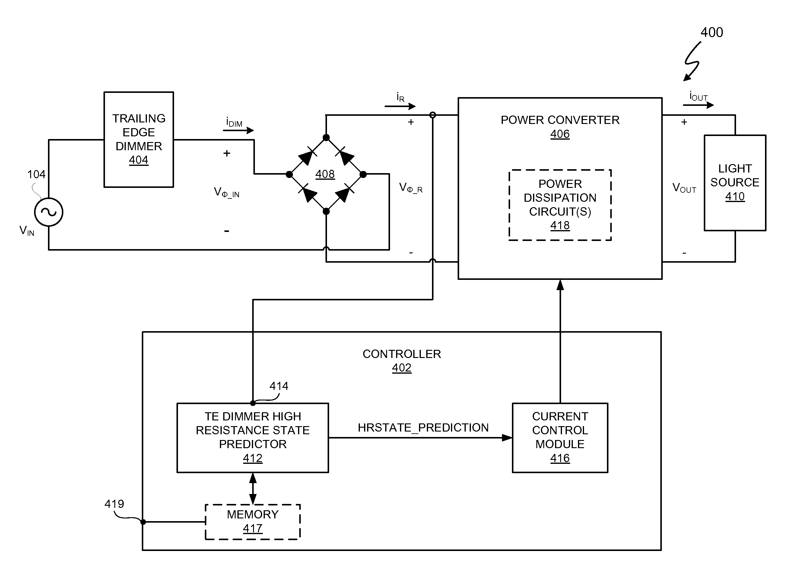
[0031]In at least one embodiment, an electronic system includes a controller, and the controller provides compatibility between an electronic light source and a trailing edge dimmer. In at least one embodiment, the controller is capable of predicting an estimated occurrence of a trailing edge of a phase cut AC voltage and accelerating a transition of the phase cut AC voltage from the trailing edge to a predetermined voltage threshold. The terms “predict” and derivatives thereof, such as “predicting” and “prediction” mean to declare or indicate in advance. Thus, in at least one embodiment, predicting an estimated occurrence of a trailing edge of a phase cut AC voltage declares or indicates in advance the estimated occurrence of the trailing edge of the phase cut AC voltage. In at least one embodiment, the controller predicts an estimated occurrence of the trailing edge of the phase cut AC voltage on the basis of actual observations from one or more previous cycles of the phase cut AC...


PUM


Abstract

In at least one embodiment, an electronic system includes a controller, and the controller provides compatibility between an electronic light source and a trailing edge dimmer. In at least one embodiment, the controller is capable of predicting an estimated occurrence of a trailing edge of a phase cut AC voltage and accelerating a transition of the phase cut AC voltage from the trailing edge to a predetermined voltage threshold. In at least one embodiment, the controller predicts an estimated occurrence of the trailing edge of the phase cut AC voltage on the basis of actual observations from one or more previous cycles of the phase cut AC voltage.

Description

CROSS-REFERENCE TO RELATED APPLICATION[0001]This application claims the benefit under 35 U.S.C. §119(e) and 37 C.F.R. §1.78 of U.S. Provisional Application No. 61 / 414,291, filed on Nov. 16, 2010, and is incorporated by reference in its entirety.BACKGROUND OF THE INVENTION[0002]1. Field of the Invention[0003]The present invention relates in general to the field of electronics, and more specifically to a method and system for trailing edge dimmer compatibility with dimmer high resistance prediction.[0004]2. Description of the Related Art[0005]The development and use of energy efficient technologies continues to be a high priority for many entities including many companies and countries. One area of interest is the replacement of incandescent lamps with more energy efficient lamps such as lamps based on electronic light sources. For this description, electronic light sources are light emitting diodes (LEDs) and compact fluorescent lamps (CFLs). The development of electronic light sourc...

Claims


Application Information

Patent Timeline
Patent Type & Authority Applications(United States)
IPC IPC(8): H05B37/02H05B44/00
CPCH05B33/0815H05B37/02H05B39/048H05B33/0851H05B45/10H05B45/3575Y02B20/00H05B45/38H05B45/3725
Inventor MELANSON, JOHN L.KING, ERIC J.
Owner SIGNIFY HLDG BV
Why Eureka
Try Eureka