Airtight assembly of two components and method for producing such an assembly

Inactive Publication Date: 2012-05-17
COMMISSARIAT A LENERGIE ATOMIQUE ET AUX ENERGIES ALTERNATIVES
View PDF0 Cites 7 Cited by
  • Summary
  • Abstract
  • Description
  • Claims
  • Application Information

AI Technical Summary

Benefits of technology

[0012]The present application, therefore, finds numerous applications, in particular concerning: (i.) C2W or W2W lidding for all types of application: bolometers, MEMS, gas detectors, hermetic optics, biochips, cooled infrared, etc; and (ii.) bolometric detection matrices with a transparent lid or provided with near-field optics (gratings, filters, etc). Since the invention makes it possible to align the lid and the detection matrix to better then + / −1 μm, it is possible to produce layers on the top or bottom face of the lid.
[0049]The contact surface between the inserts is maximised compared with the soldering volume involved. It is, therefore, possible to recover the solder in a “solder reservoir” situated at the bottom of the female tube, namely the hollow inserts.

Problems solved by technology

However, said components cannot tolerate such thermal stresses.
Moreover, the techniques proposed require the application of a force during the airtight sealing.
H-lowever, some components cannot tolerate such mechanical stresses.

Method used


Image

  • Airtight assembly of two components and method for producing such an assembly
  • Airtight assembly of two components and method for producing such an assembly
  • Airtight assembly of two components and method for producing such an assembly

Examples


Embodiment Construction

[0061]Embodiments of the invention will be illustrated below by way of a particular application relating to the lidding of chips of the bolometer type using a functionalised lid. In this application, and as will be detailed below, a double-insert bead is used.

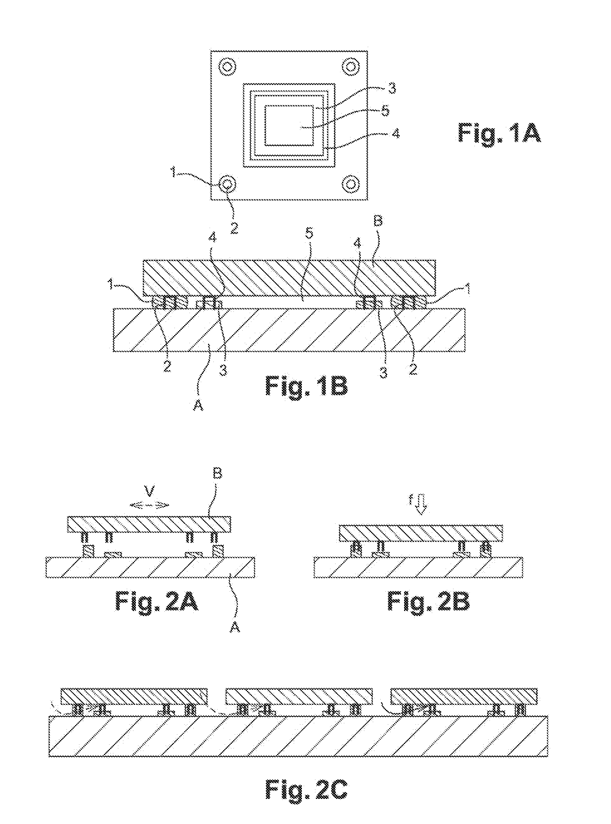
[0062]By way of dimensions of the characteristic elements of the invention, the following example can be given: distance between the bead 3 and the spacer 1 is 100 μm, width of bead 3 is 100 μm, width of the bead insert 4 is 80 μm, and any horizontal offset between the bead insert 4 and the bead 3 is 10 μm.

Components Before Assembly

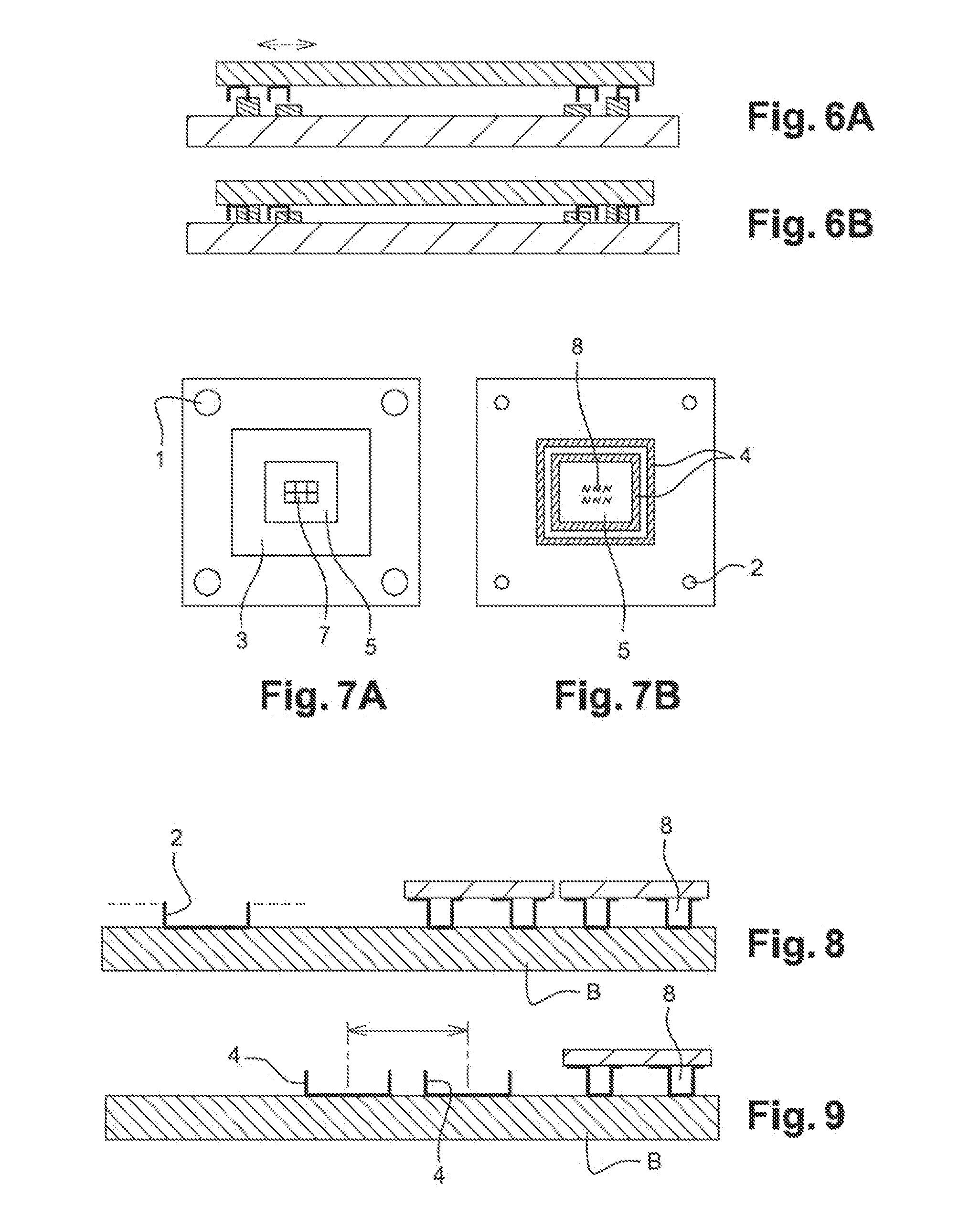
[0063]The example relates to bolometric detection matrices with transparent lid or provided with near-field optics (gratings, filters, etc).

[0064]The aim sought is to align the lid and the detection matrix to better than + / −1 μm and to produce filtering layers on the top or bottom surface of the lid, so as to obtain an infrared spatial spectrometer. Plan views of the components before assembly are il...


PUM

PropertyMeasurementUnit
Temperatureaaaaaaaaaa
Flexibilityaaaaaaaaaa
Heightaaaaaaaaaa

Abstract

An airtight assembly of two components including a first component with a support having at its surface: at least one spacer composed of a ductile material, arranged at the periphery of the component, and at least one bead composed of a ductile material; a second component with a support having at its surface: at least one insert inserted over the whole or part of its surface in the spacer on the first component, and at least one bead insert inserted over all or part of the surface thereof in the bead on the first component, defining an airtight central cavity.

Description

CROSS-REFERENCE TO RELATED APPLICATIONS[0001]The present application is a National Stage Application of PCT International Application No. PCT / FR2010 / 051561 (filed on Jul. 23, 2010), under 35 U.S.C. §371, which claims priority to French Patent Application No. 0955658 (filed on Aug. 13, 2009), which are each hereby incorporated by reference in their respective entireties.FIELD OF THE INVENTION[0002]The technical field to which the invention relates is that of microelectronics. Embodiments of the present invention concerns, more particularly, devices requiring simultaneously the vertical connection (better known by the expression “flip-chip”) of two components and an airtight protection of the components of the SOC (the acronym for the expression “System on Chip”) type.[0003]The present invention has a special advantage for devices that are not capable of withstanding high packaging temperatures, functioning in a special atmosphere or requiring thorough protection against external atta...

Claims


Application Information

Patent Timeline
IPC IPC(8): H05K5/06H05K13/00
CPCB81C1/00269B81C2203/0109B81C2203/019B81C2203/038H01L2224/73103Y10T29/49826H01L2224/81193H01L2924/1461H01L2924/00012H01L2924/00H01L2224/29011H01L2224/73203
Inventor MARION, FRANCOISARNAUD, AGNESDUMONT, GEOFFROYIMPERINETTI, PIERRE
Owner COMMISSARIAT A LENERGIE ATOMIQUE ET AUX ENERGIES ALTERNATIVES
Why Eureka
Try Eureka