Backlight Unit and Display Device
a backlight unit and display device technology, applied in the field of backlight units, can solve problems such as display defect, and achieve the effects of reducing light leakage, improving light use efficiency, and relieving color mixture problems
- Summary
- Abstract
- Description
- Claims
- Application Information
AI Technical Summary
Benefits of technology
Problems solved by technology
Method used
Image
Examples
embodiment 1
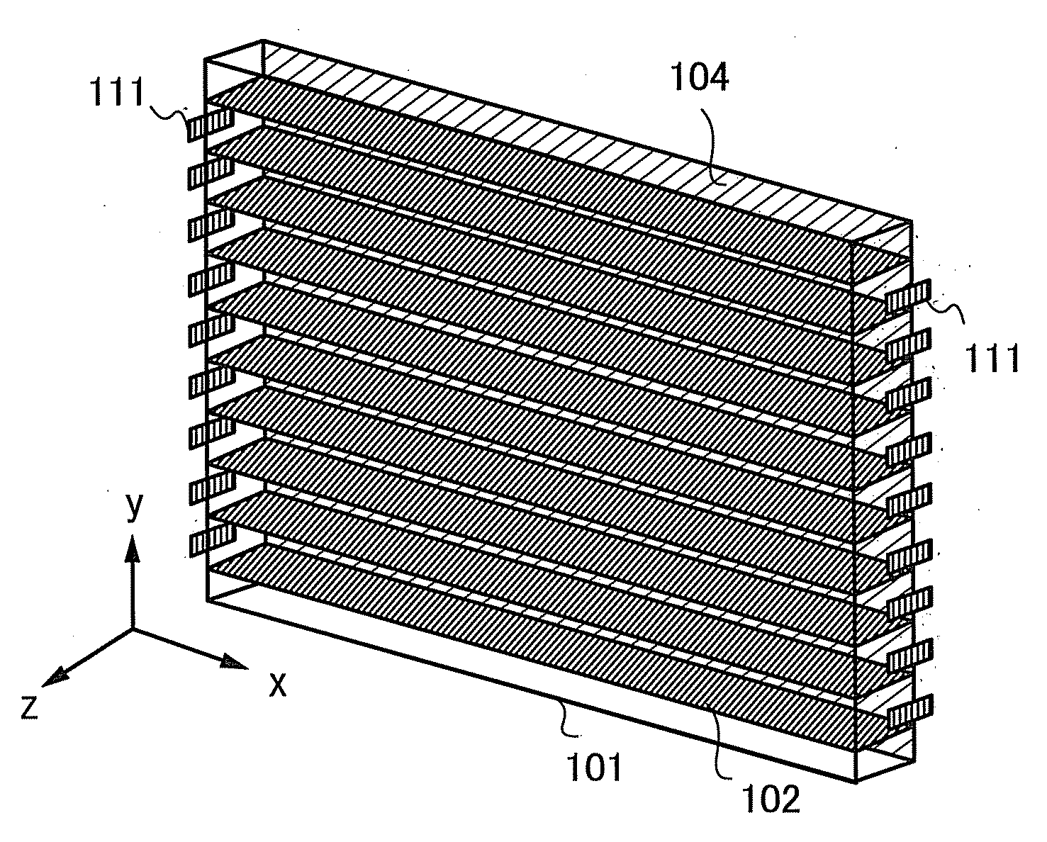
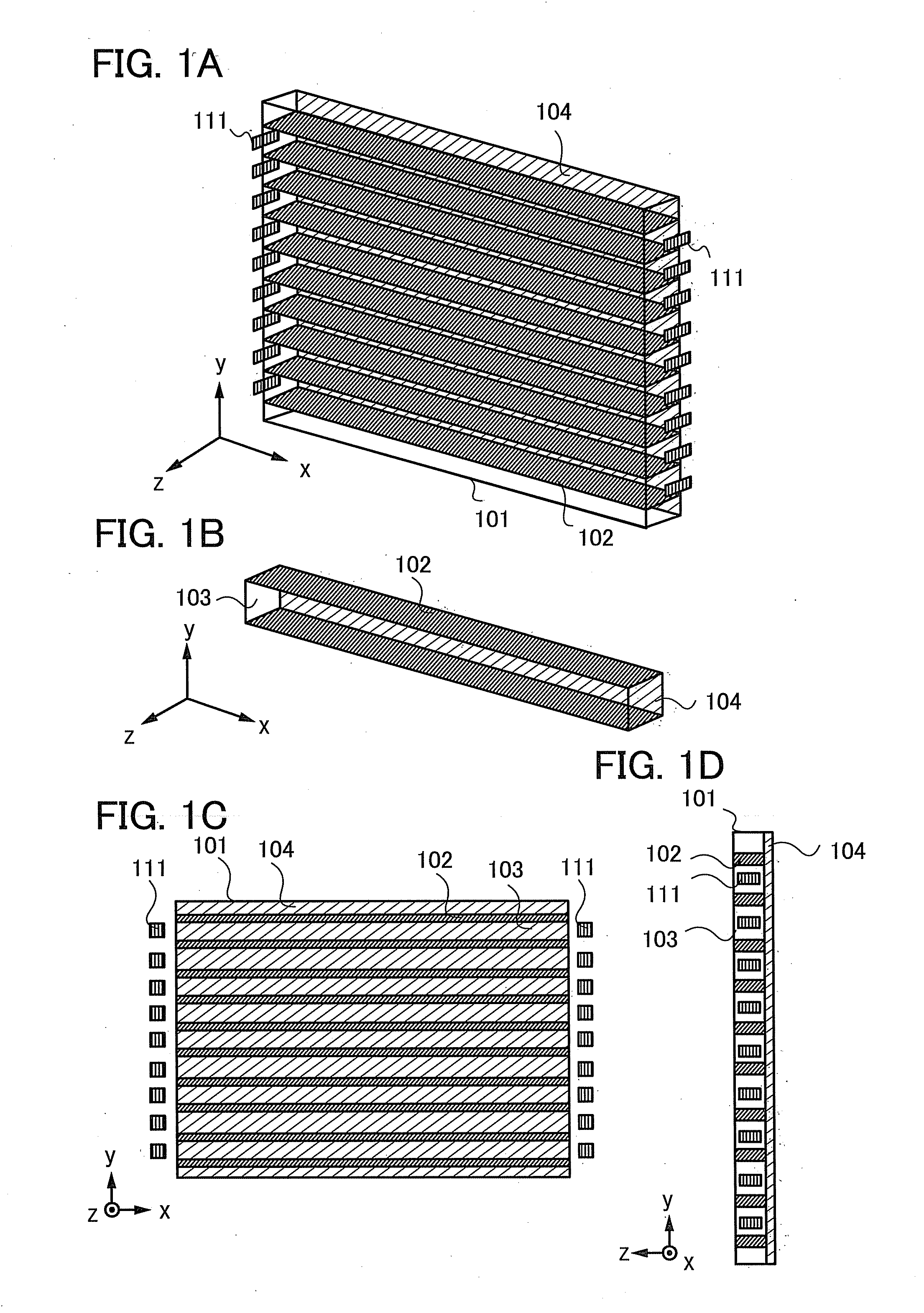
[0053]The structure of a backlight unit in one embodiment of the present invention will be described. FIGS. 1A to 1D are schematic views of the backlight unit. FIG. 1A is a perspective view that schematically illustrates the backlight unit. FIG. 1B is a perspective view that schematically illustrates a part of the backlight unit in FIG. 1A. FIG. 1C is a schematic diagram in which the backlight unit shown in FIG. 1A is viewed in the z direction. FIG. 1D is a schematic diagram in which the backlight unit in FIG. 1A is viewed in the x direction. Note that the backlight unit emits light in the z direction.
[0054]As illustrated in FIGS. 1A to 1D, the backlight unit includes a light guide plate 101 and light sources 111. The light guide plate 101 includes reflective walls 102, transparent layers 103, and a reflective layer 104.
[0055]Each reflective wall 102 is a column that has height in the direction (the z direction in the diagram) perpendicular to a bottom face of the light guide plate ...
embodiment 2
[0067]This embodiment describes one embodiment of the structure of a connecting point between the light guide plate 101 and the light sources 111 in the backlight unit having the structure described with reference to FIGS. 1A to 1D in Embodiment 1, with reference to FIGS. 4A to 4C. The reference numerals used in FIGS. 1A to 1D will be used for the description.
[0068]FIGS. 4A to 4C show, for the description, enlarged views of two adjacent reflective walls 102, a portion near the edge of the transparent layer 103, and a corresponding light source 111. In practice, as illustrated in FIGS. 1A, 1C, and 1D, the plurality of reflective walls 102, the plurality of transparent layers 103, and the plurality of light sources 111 can have the same structures as those in FIGS. 4A to 4C.
[0069]One embodiment of the structure of a connecting point between the light guide plate 101 and the light sources 111 is illustrated in FIG. 4A. The backlight unit includes a reflective mirror 141. The reflective...
embodiment 3
[0074]This embodiment describes one embodiment of the structure of the light source 111 in the backlight unit having the structure described with reference to FIGS. 1A to 1D in Embodiment 1, with reference to FIGS. 5A to 5I.
[0075]The light source 111 can be formed by the combination of a plurality of light sources, e.g., the combination of light sources of colors that produce white by addictive color mixture. For example, the light source 111 can be formed by the combination of a red light source (R), a green light source (G), and a blue light source (B). For another example, the light source 111 can be formed by the combination of a red light source (R), a green light source (G), a blue light source (B), and a light source of another color. The other color may be one or more of the following: yellow, cyan, magenta, and the like. Alternatively, the other color may be white. The light source can be a light-emitting diode, an organic EL element, or the like.
[0076]FIGS. 5A to 5C each i...
PUM
 Abstract
Description
Claims
Application Information
 - R&D
- Intellectual Property
- Life Sciences
- Materials
- Tech Scout
- Unparalleled Data Quality
- Higher Quality Content
- 60% Fewer Hallucinations
Browse by: Latest US Patents, China's latest patents, Technical Efficacy Thesaurus, Application Domain, Technology Topic, Popular Technical Reports.
© 2025 PatSnap. All rights reserved.Legal|Privacy policy|Modern Slavery Act Transparency Statement|Sitemap|About US| Contact US: help@patsnap.com


