
Earphone antenna device for receiving dual band signal

a dual-band signal and antenna technology, applied in the direction of antenna equipment with additional functions, separate antenna unit combinations, electric transducers, etc., can solve the problems of significant limitations in antenna performance, increased mounting space and cost of components, and increased cost of components, so as to reduce the number of antennas and manufacturing costs, improve the performance of mobile terminals

Inactive Publication Date: 2012-05-17
SAMSUNG ELECTRONICS CO LTD
View PDF8 Cites 15 Cited by
  • Summary
  • Abstract
  • Description
  • Claims
  • Application Information

AI Technical Summary

Benefits of technology

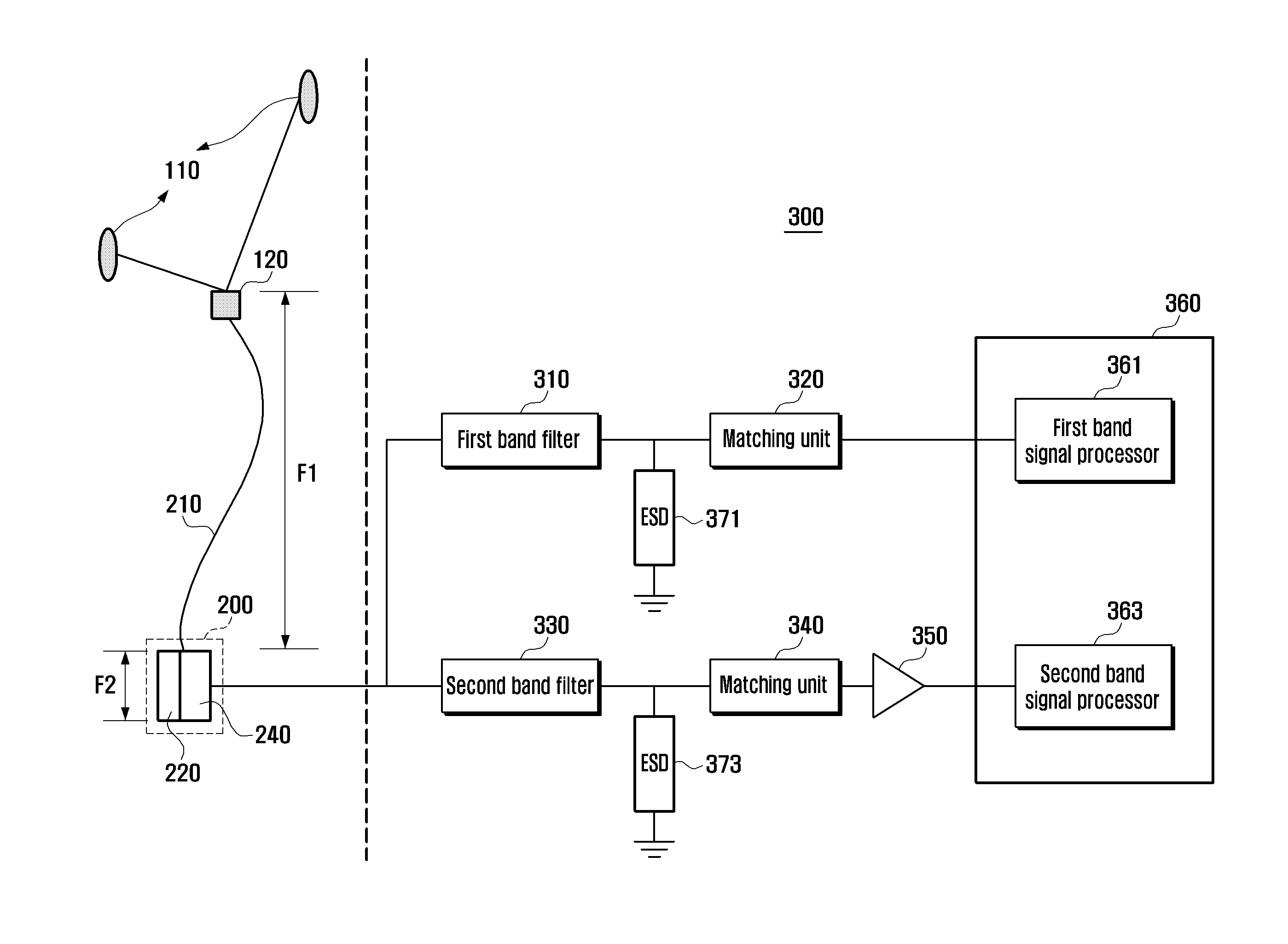
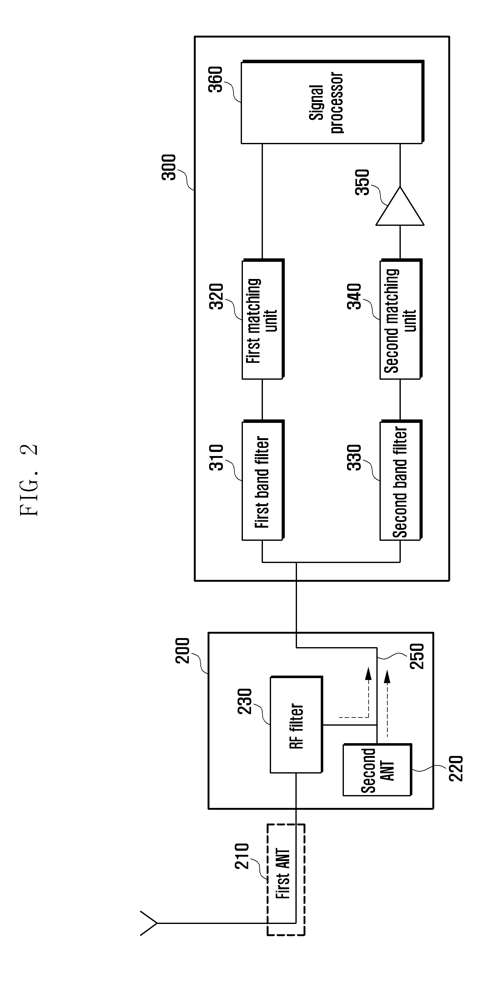
[0009]Aspects of the present invention are to address at least the above-mentioned problems and / or disadvantages and to provide at least the advantages described below. Accordingly, an aspect of the present invention is to provide an earphone antenna device that includes multiple antennas for receiving multiple frequency signals in an earphone device, and is designed with a structure in which an antenna receiving a higher frequency involves a part of another antenna receiving a lower frequency, thereby improving the performance of a mobile terminal, and reducing the number of antennas and manufacturing costs. In a case of a terminal supporting S-DMB / T-DMB broadcasting, an earphone-antenna being a T-DMB antenna is implemented to share one side of a path with the S-DMB antenna.
[0012]An earphone antenna device according to an exemplary embodiment of the present invention includes and integrates multiple antennas to reduce the number of components, thereby reducing the cost.

Problems solved by technology

Accordingly, in a mobile terminal including a DMB function, as the number of antennas is increased, the mounting space and costs of a component are also increased.
As described above, a mobile terminal receiving signals of multiple frequencies is significantly limited by antenna performance due to the implementation of multiple antennas and causes performance problems.

Method used


Image

  • Earphone antenna device for receiving dual band signal
  • Earphone antenna device for receiving dual band signal
  • Earphone antenna device for receiving dual band signal

Examples


Embodiment Construction

[0020]The following description with reference to the accompanying drawings is provided to assist in a comprehensive understanding of exemplary embodiments of the invention as defined by the claims and their equivalents. It includes various specific details to assist in that understanding but these are to be regarded as merely exemplary. Accordingly, those of ordinary skill in the art will recognize that various changes and modifications of the embodiments described herein can be made without departing from the scope and spirit of the invention. In addition, descriptions of well-known functions and constructions may be omitted for clarity and conciseness.

[0021]The terms and words used in the following description and claims are not limited to the bibliographical meanings, but, are merely used by the inventor to enable a clear and consistent understanding of the invention. Accordingly, it should be apparent to those skilled in the art that the following description of exemplary embod...


PUM


Abstract

An earphone antenna device is provided. The earphone antenna device includes a first antenna connected to an earphone, configured in the form of a wire that is separate from an audio line, for receiving a first band frequency, and a connector connecting the earphone to a terminal device. The connector includes a Radio Frequency (RF) connected to the first antenna, for filtering the first band frequency and for restraining other band frequencies, and a second antenna connected between the RF filter and an internal path of the connector connected to the terminal device, for receiving a second band frequency higher than the first band frequency.

Description

PRIORITY[0001]This application claims the benefit under 35 U.S.C. §119(a) of a Korean patent application filed on Nov. 11, 2010 in the Korean Intellectual Property Office and assigned Serial No. 10-2010-0111956, the entire disclosure of which is hereby incorporated by reference.BACKGROUND OF THE INVENTION[0002]1. Field of the Invention[0003]The present invention relates to an earphone antenna device. More particularly, the present invention relates to an earphone antenna device for receiving a dual band signal.[0004]2. Description of the Related Art[0005]In recent years, in the trend of digital convergence, antennas for portable broadcasting (e.g., Terrestrial-Digital Multimedia Broadcasting (T-DMB), Satellite-DMB (S-DMB), and the like), a Global Positioning System (GPS) and Connectivity (e.g., Bluetooth, Radio Frequency Identification (RFID), Near Field Communication (NFC), Zigbee, Ultra Wideband (UWB), Electronic Fee Collection (EFC)), as well as mobile communication antennas for ...

Claims


Application Information

Patent Timeline
Patent Type & Authority Applications(United States)
IPC IPC(8): H04R1/10H01Q5/314
CPCH04R1/10H04R2420/07H01Q5/314H01Q21/30H01Q1/44H01Q1/273H01Q1/46
Inventor JANG, KWANG SEOK
Owner SAMSUNG ELECTRONICS CO LTD
Learn More