
Rotor and method for manufacturing a rotor for a turbo machine

Inactive Publication Date: 2012-05-17
MTU AERO ENGINES GMBH
View PDF47 Cites 7 Cited by
  • Summary
  • Abstract
  • Description
  • Claims
  • Application Information

AI Technical Summary

Benefits of technology

[0006]The object of the present invention is to create a rotor of the type named initially, which has an improved vibration behavior. Another object of the invention is to create a method for manufacturing a rotor having an improved vibration behavior.

Problems solved by technology

Because of their position relative to the vibrating system, these damping elements, however, frequently do not offer sufficient damping of the different forms of vibration.
Since the damping element not only damps vibrations, but simultaneously must seal a relatively large surface, both the damping element and the rotating blade are subject to high structural limitations.
This solution, however, in particular, has the disadvantage that the wire-like damping element is found in the flow path or annular channel.
In particular, this solution is not applicable or is only conditionally applicable in the case of internally cooled blades.
This solution, however, is not suitable for rotors without an external shroud.
Further, an optimal adjustment of the vibration damping is also not possible with this system.

Method used


Image

  • Rotor and method for manufacturing a rotor for a turbo machine
  • Rotor and method for manufacturing a rotor for a turbo machine
  • Rotor and method for manufacturing a rotor for a turbo machine

Examples


Embodiment Construction

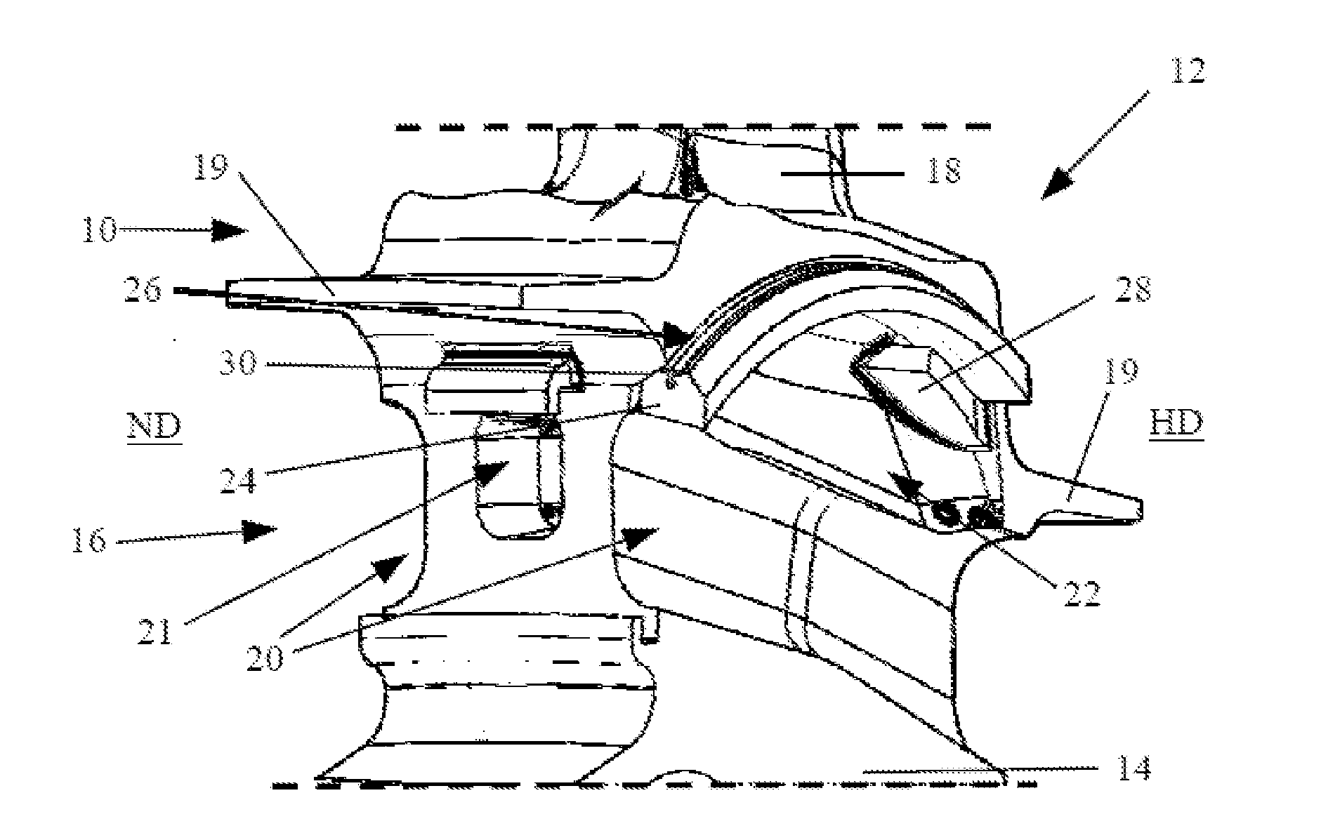
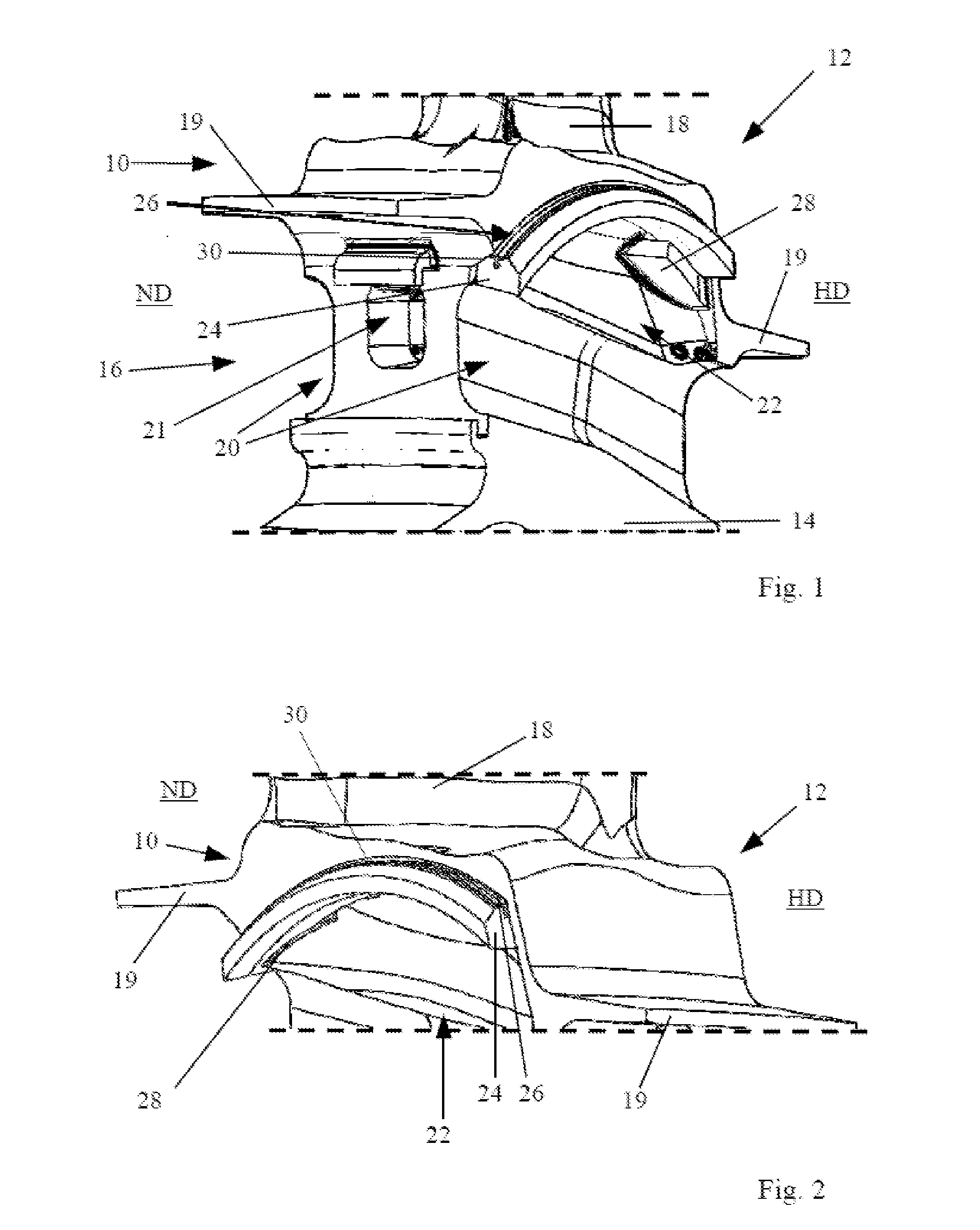
[0028]FIG. 1 shows a schematic and partially cut-away perspective view of a blade platform 10 of a rotating blade 12 viewed from the low-pressure (ND) side of a rotor. FIG. 1 will be explained in the following in conjunction with FIG. 2, in which a schematic perspective view of blade platform 10 shown in FIG. 1 is illustrated, viewed from the high-pressure (HD) side of the rotor.

[0029]The rotor, which is designed presently in integral BLISK (Bladed Disk) construction for a turbine stage of an aircraft engine, comprises a basic rotor body 14, which is joined cohesively in a way known in and of itself with several rotating blades 12. A radially inner region (relative to an axis of rotation of the rotor) of a blade element 18 connecting to blade platform 10 can be recognized in FIG. 1 for the illustrated rotating blade 12. Blade platform 10, both on the low-pressure (ND) side as well as on the high-pressure (HD) side of the rotor, forms a blade shroud 19 for at least partially demarcat...


PUM

PropertyMeasurementUnit
Pressureaaaaaaaaaa

Abstract

The invention relates to a rotor for a turbo machine, having rotating blades (12), which are joined to a basic rotor body (14), whereby a damping element (24) for damping blade vibrations is provided between blade platforms (10) of at least two adjacent rotating blades (12), damping element (24) being arched radially upward along its axial extent relative to an axis of rotation of the rotor. In addition, the invention relates to a method for manufacturing, repairing, and / or overhauling a rotor for a turbo machine, in which rotating blades (12) are joined to a basic rotor body (14), whereby a damping element (24) for damping blade vibrations is disposed between at least two adjacent rotating blades (12). In this case, damping element (24) is arched radially upward along its axial extent relative to an axis of rotation of the rotor.

Description

BACKGROUND OF THE INVENTION[0001]The invention relates to a rotor of the type indicated in the preamble of patent claim 1 for a turbo machine as well as a turbo machine having a rotor. In addition, the invention relates to a method of the type indicated in the preamble of patent claim 12 for manufacturing a rotor for a turbo machine.[0002]This type of rotor is already known from the prior art and comprises damping elements for damping blade vibrations that are introduced into through-channels or relief channels on the side of the blade neck between adjacent blades as so-called under-platform dampers. Because of their position relative to the vibrating system, these damping elements, however, frequently do not offer sufficient damping of the different forms of vibration.[0003]EP 1 795 703 A2 discloses a bladed rotor, in which, below its respective blade platform, each rotating blade has a cooling chamber, into which the cooling air is conducted during the operation of the associated ...

Claims


Application Information

Patent Timeline
IPC IPC(8): F04D29/66B23P6/00
CPCF01D5/22F01D11/006F04D29/321F04D29/668Y10T29/49318Y02T50/673Y02T50/676F01D5/187Y10T29/49321Y02T50/671Y02T50/60
Inventor BORUFKA, HANS PETERSTIEHLER, FRANK
Owner MTU AERO ENGINES GMBH
Learn More