
Computer System, Program, and Method for Assigning Computational Resource to be Used in Simulation

Inactive Publication Date: 2012-05-17
HITACHI LTD
View PDF12 Cites 39 Cited by
  • Summary
  • Abstract
  • Description
  • Claims
  • Application Information

AI Technical Summary

Benefits of technology

[0011]The present invention has been developed in view of the above problems and an object is to suppress cost required for introduction and maintenance of a development environment including a plurality of simulators, share design information and facilitate adjustment of parameters of the simulators.
[0015]Accordingly, since an aspect of the present invention allows simulators or software to be all managed on a server system, embedded system developers need not purchase them in advance and maintain them. Further, since developed software and simulation results using the software are managed on the server system, it becomes easier to share design files and a risk of leaking information to outsiders can be suppressed to a minimum level.
[0016]Further, since the developers can easily execute quick and accurate simulations without requiring detailed know-how due to the cooperation of a plurality of simulators and automated adjustment of simulator parameters, development efficiency of the embedded system is improved.

Problems solved by technology

The technology of the above patent literature 1 can solve the fourth and fifth ones of the above problems, but cannot solve the other problems and service users need to individually deal with them.
As described above, the first problem is that it is difficult to share design files and manage progresses due to the simultaneous development at a plurality of sites.
Further, the second problem is that cost for manually adjusting the individual simulators and connection parameters among the simulators increases since different simulators need to be connected.
Furthermore, the third problem is that cost for introduction and maintenance of the hardware and the software is high and it is difficult to easily execute a simulation since a plurality of simulators and computational resources are necessary.

Method used


Image

  • Computer System, Program, and Method for Assigning Computational Resource to be Used in Simulation
  • Computer System, Program, and Method for Assigning Computational Resource to be Used in Simulation
  • Computer System, Program, and Method for Assigning Computational Resource to be Used in Simulation

Examples


first embodiment

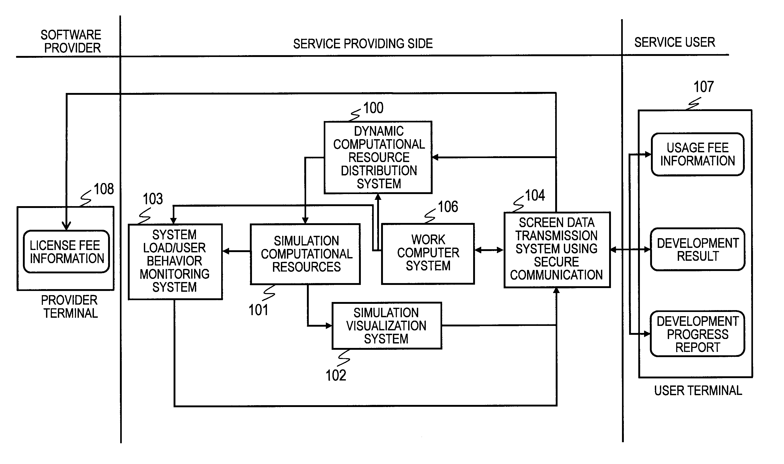
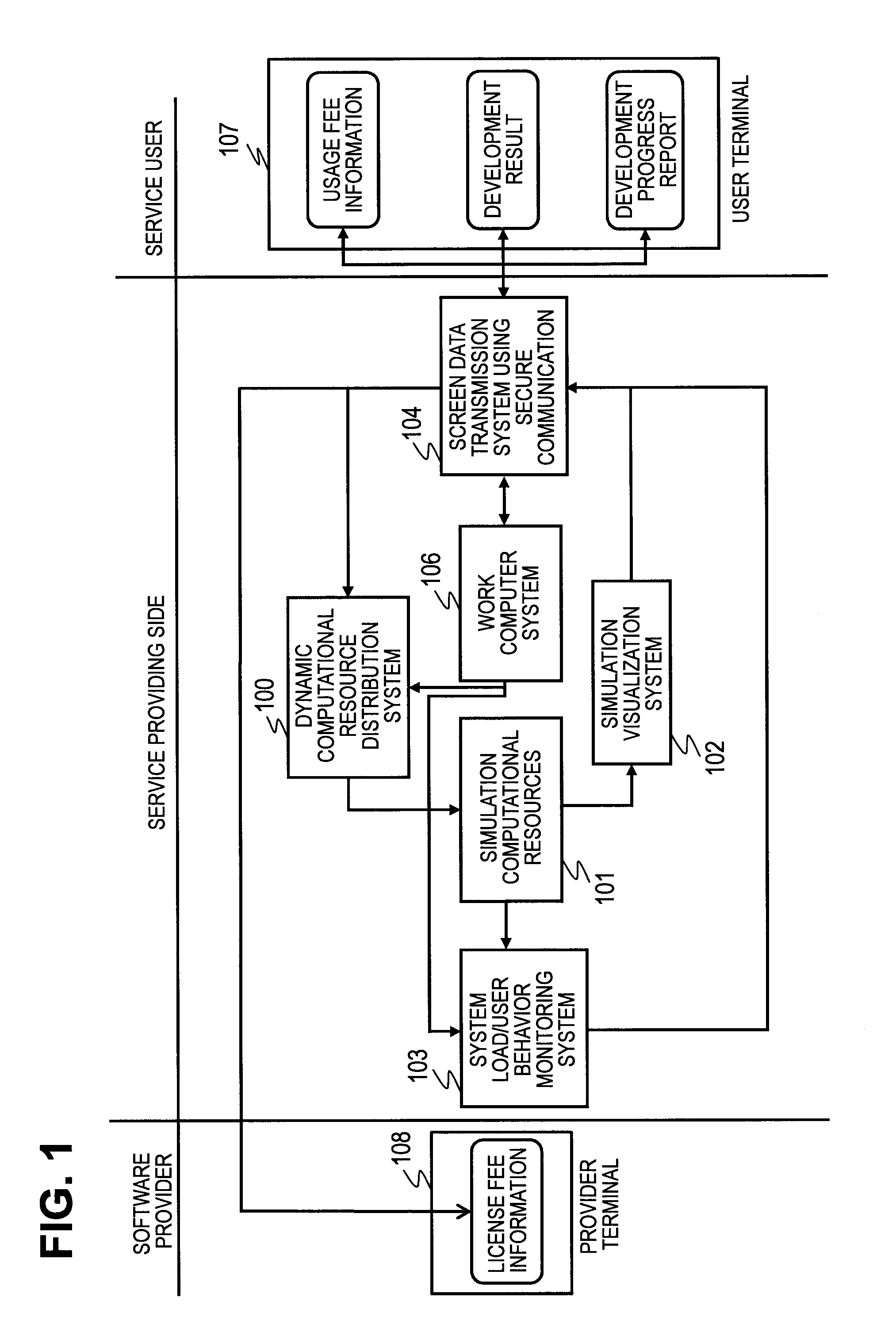
[0049]Hereinafter, one embodiment of the present invention is described based on the accompanying drawings. FIG. 1 is a functional block diagram schematically showing one example of the embodiment of the present invention and a computer system (development assisting system for embedded devices) for assisting the development of an embedded system.

[0050]In a computer system used to develop an embedded system, a dynamic computational resource distribution system 100, simulation computational resources 101, a simulation result visualization system 102, a system load / user behavior monitoring system 103, a work computer system 106, a screen data transmission system 104 using secure communication, a user terminal 107 and a software provider terminal 108 are connected via an internal network.

[0051]The above configuration is called the present system below. The user terminal 107 and the software provider terminal 108 can access the present system only via the screen data transmission system ...

second embodiment

[0245]FIG. 29 is a block diagram schematically showing an example of a second embodiment of the present invention. The second embodiment includes a high-security file transmission system 105 in addition to the configuration of the first embodiment. A user terminal 107 or a provider terminal 108 can receive a system usage report, a license fee report, a development progress report and a software usage status report provided from a system load / user behavior monitoring system 103 via the high-security file transmission system 105.

[0246]This eliminates the need to directly connect the user terminal 107 and the provider terminal 108 to the system load / user behavior monitoring system 103 of the present system in obtaining and confirming the reports. This eliminates the need to connect the user terminal 107 and the like to a dynamic computational resource distribution system 100, a simulation computational resources 101, a simulation result visualization system 102 and the system load / user...


PUM


Abstract

The cost necessary for introducing and maintaining a development environment that includes multiple simulators is suppressed, and a sharing of designing information is promoted, to make parameter adjustment of simulators easy. Provided is a service that unifies development environment on a computer provided with: a working computer system that can guarantee that there is no leaking of designing files; a user behavior monitoring system that collects utilization history of simulators or software, for each of the users, and selects development process of each of the users from the collected information; and a dynamic computational-resource distribution system that can conduct an automatic optimization of a complex simulation configuration, from information collected by the aforementioned user behavior monitoring system.

Description

BACKGROUND OF THE INVENTION[0001]The present invention relates to a technology used in a development environment, in which a plurality of simulators execute a coordinated complicated simulation in the development of an embedded system.[0002]An embedded system is a system composed of a mechanism constituting a control object, hardware for performing a control operation based on a physical quantity received from the mechanism and outputting a control value to the mechanism, and software which operates on the hardware. For example, an embedded system of an automotive vehicle is composed of an engine as a control object, an electronic device such as a microcomputer for controlling the engine, and software which operates on the microcomputer. Since the behavior of the software included in the embedded system strongly depends on the mechanism of the control object and the configuration of the hardware, it is necessary to analyze combined behavior of the mechanism, the hardware and the sof...

Claims


Application Information

Patent Timeline
IPC IPC(8): G06F17/50
CPCG06F11/3664G06F9/5055
Inventor ITO, YASUHIROSUGURE, YASUOOHO, SHIGERUKURATA, HIDEAKI
Owner HITACHI LTD
Learn More