
Supersonic nozzle for boiling liquid

Inactive Publication Date: 2012-05-24
FISONIC HLDG
View PDF2 Cites 7 Cited by
  • Summary
  • Abstract
  • Description
  • Claims
  • Application Information

AI Technical Summary

Benefits of technology

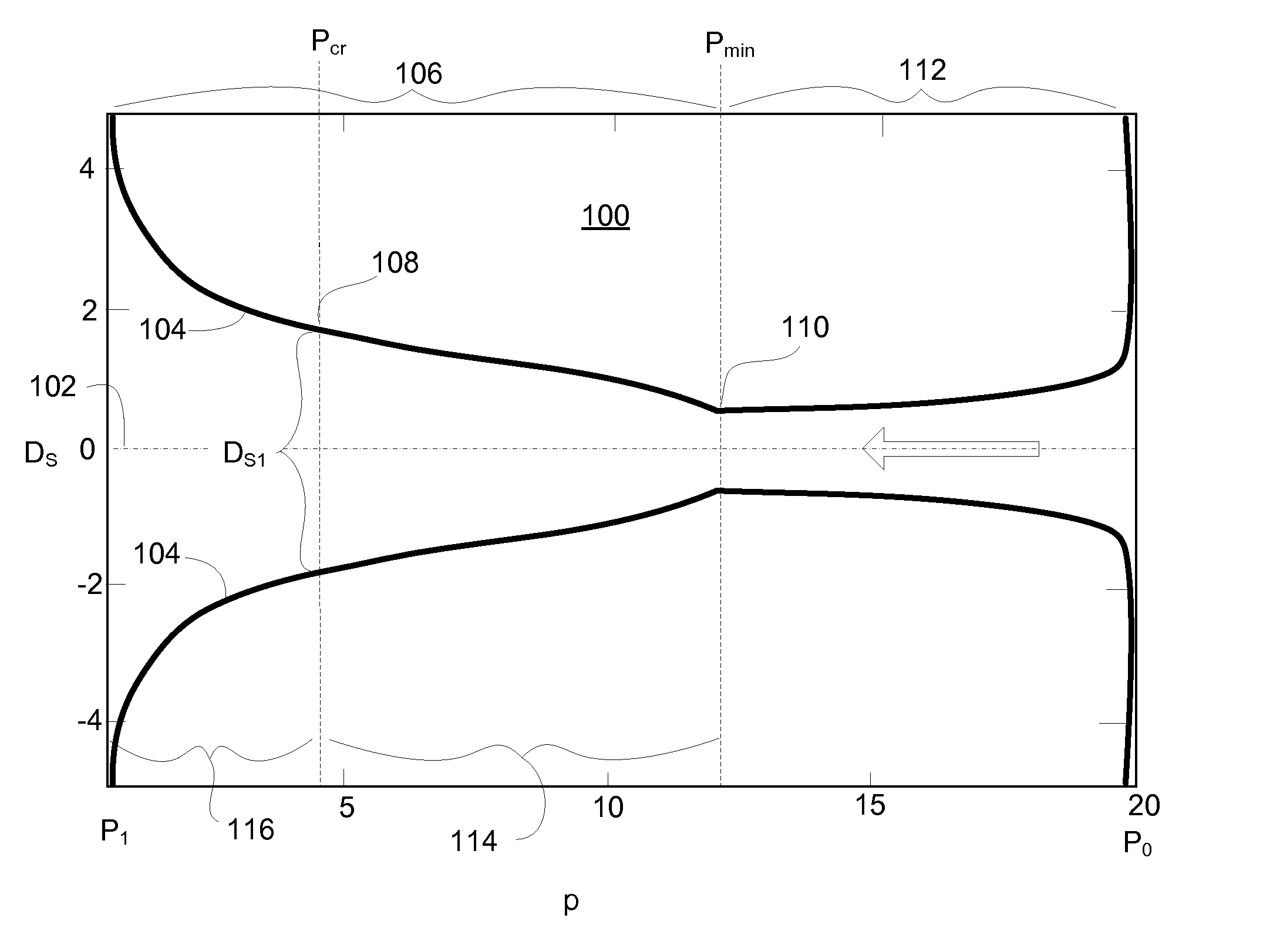
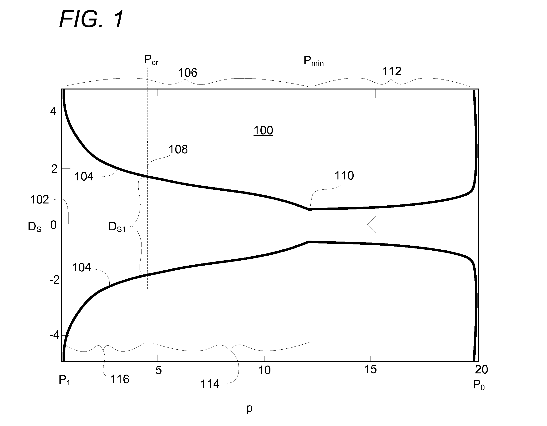
[0007]A new design for a supersonic nozzle is disclosed. The new nozzle is capable of improving conversion efficiency of the pressure energy of the input medium into kinetic energy of a two-phase gas-liquid stream of the ejected medium, as compared to prior art nozzles. These and related advantages are achieved using the new supersonic nozzle of specific design as disclosed herein. Like a traditional de Laval nozzle, the new supersonic nozzle for boiling liquid includes inlet and outlet sections that are respectively converging and diverging in the direction of the medium flow, between which a minimal nozzle section, sometimes called a “throat,” is located. However, unlike traditional nozzles, in the new nozzle the generating line of the fore part of the diverging section of the nozzle is formed by a curve that is concave to the nozzle axis and smoothly transitions to a curve that is convex to the nozzle axis in the critical nozzle section downstream of the nozzle throat. Surprisingly, when a traditional de Laval type nozzle design is modified according to the specific parameters as disclosed herein, the nozzle allows for efficient conversion of pressure energy into kinetic energy of the media stream, under circumstances wherein a two-phase medium is formed during boiling of an input liquid medium due to the pressure drop inside of the nozzle below the saturation pressure of the liquid medium. These advantages are realized without any hydraulic losses or design complications associated with prior nozzles that include a steam-generating element.

Problems solved by technology

However, the de Laval nozzle does not allow an efficient conversion of pressure energy into kinetic energy of the media stream, particularly in the event that the liquid is fed to the inlet of the supersonic nozzle and a two-phase medium is formed during its boiling due to the pressure drop inside of the nozzle below the saturation pressure.
However, the steam-generating element complicates the nozzle design, and increases hydraulic losses in the flow channel of the nozzle.
This nozzle therefore does not optimize operation of the nozzle leaving its profile in the diverging section as in the traditional de Laval nozzle profile.

Method used


Image

  • Supersonic nozzle for boiling liquid
  • Supersonic nozzle for boiling liquid
  • Supersonic nozzle for boiling liquid

Examples


Embodiment Construction

[0010]Referring to FIG. 1, it should be appreciated that a nozzle 100 according to the present technology, sometimes called a Fisenko nozzle, is cylindrically symmetric around its central longitudinal axis 102, and the profile 104 represents a cross-section taken through such axis 102. The nozzle body may be constructed of any durable material compatible with the intended medium and working temperatures; for example, stainless steel or other metal alloys; ceramic; structural polymers; or various composite materials. The nozzle 100 may be formed in any suitable method to provide the nozzle profile as shown and described.

[0011]As noted above, in the new nozzle 100 the generating line for a proximal part of the diverging section 106 of the nozzle is formed by a curve 104 that is concave to the nozzle axis 102 in a concave section 114 and smoothly transitions to a curve that is convex to the nozzle axis in a convex section 116 downstream of the critical nozzle section 108, which is, in ...


PUM


Abstract

A supersonic nozzle (called a Fisenko nozzle) improves conversion efficiency of the pressure energy of the input medium into kinetic energy of a two-phase gas-liquid stream of the ejected medium. The nozzle for boiling liquid includes inlet and outlet sections that are respectively converging and diverging in the direction of the medium flow, between which is a minimal nozzle section. The profile for a proximal part of the diverging section of the nozzle is defined by a curve that is concave to the nozzle axis, which smoothly transitions to a curve that is convex to the nozzle axis through the critical nozzle section downstream of the nozzle minima. At the critical section, the flow reaches sonic velocity and the nozzle profile is neither convex nor concave.

Description

BACKGROUND[0001]1. Field[0002]The present disclosure relates to fluidics, and more particularly to a nozzle apparatus for dispersal of different media using a homogenous two-phase stream of a medium, such as a boiling liquid.[0003]2. Description of Related Art[0004]A de Laval nozzle in the form of a converging-diverging channel for creation of a supersonic flow by passing a working medium through this channel under action of longitudinal pressure drop between the channel inlet and outlet is known in certain applications; for example got solid-propellant rocket engines. A de Laval nozzle is characterized by inlet and outlet sections that are respectively converging and diverging in the direction of the medium flow, between which a minimal cross-section is located. However, the de Laval nozzle does not allow an efficient conversion of pressure energy into kinetic energy of the media stream, particularly in the event that the liquid is fed to the inlet of the supersonic nozzle and a tw...

Claims


Application Information

Patent Timeline
IPC IPC(8): B05B1/00
CPCF04F5/46
Inventor FISENKO, VLADIMIR VLADIMIROVICH
Owner FISONIC HLDG
Learn More