High yield ladle bottoms

a technology of metallurgical vessels and ladles, which is applied in the direction of furnace floors, manufacturing converters, furnaces, etc., can solve the problems of certain amount of liquid metal remaining in the ladle, lower quality steel, etc., and achieve the effect of reducing the volume of molten metal remaining, reducing the amount of slag entrained, and increasing the yield of molten metal

Active Publication Date: 2012-05-24
HARBISONWALKER INT INC
View PDF1 Cites 18 Cited by
  • Summary
  • Abstract
  • Description
  • Claims
  • Application Information

AI Technical Summary

Benefits of technology

[0012]An advantage of the present invention is the provision of a refractory bottom lining for a ladle used in a steel making process
[0013]Another advantage of the present invention is the provision of a refractory bottom lining, as described above that aids in the flow of molten metal in the ladle as the molten metal is drained from the ladle.
[0014]Another advantage of the present invention is the provision of a bottom lining, as described above that is designed to minimize the amount of slag entrained in the molten metal as the molten metal is drained from the ladle.
[0015]A still further advantage of the present invention is the provision of a bottom lining, as described above that captures slag on sections of the bottom lining as the molten metal is drained from the ladle.
[0016]Still another advantage of the present invention is the provision of a bottom lining, as described above that reduces the volume of molten metal remaining in the ladle when the flow of molten metal from the ladle ceases.
[0017]Still another advantage of the present invention is the provision of a bottom lining, as described above that increases a yield of molten metal by allowing more slag-free, molten metal to be drained from the ladle.

Problems solved by technology

The slag particles cause contamination of the liquid metal thereby causing the resulting steel to be of lower quality.
This results in a certain amount of liquid metal being left in the ladle.

Method used


Image

  • High yield ladle bottoms
  • High yield ladle bottoms
  • High yield ladle bottoms

Examples


first embodiment

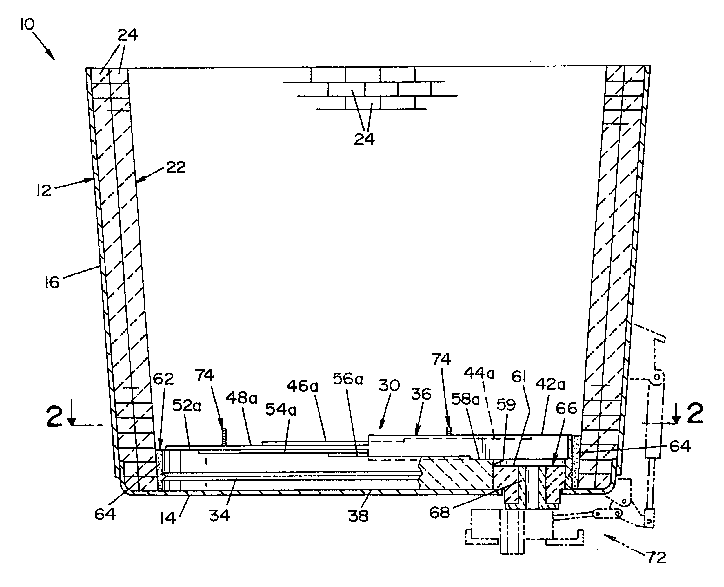
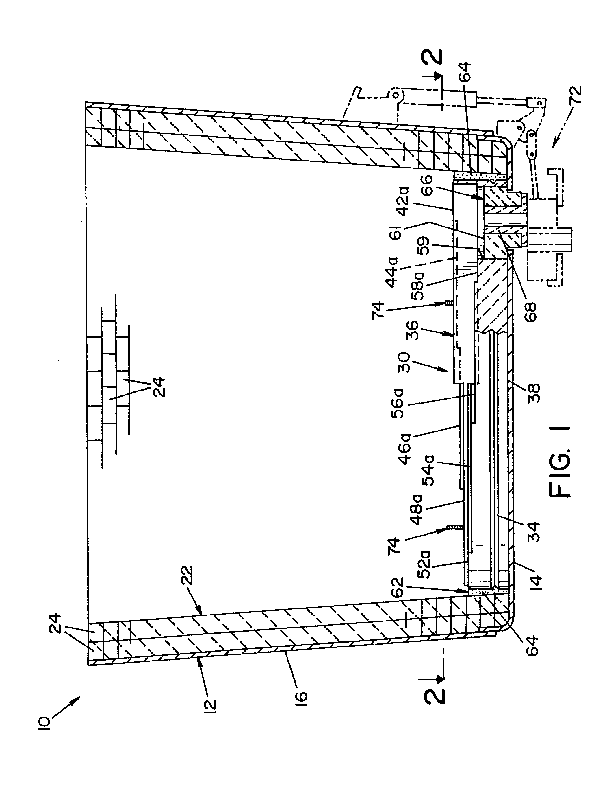
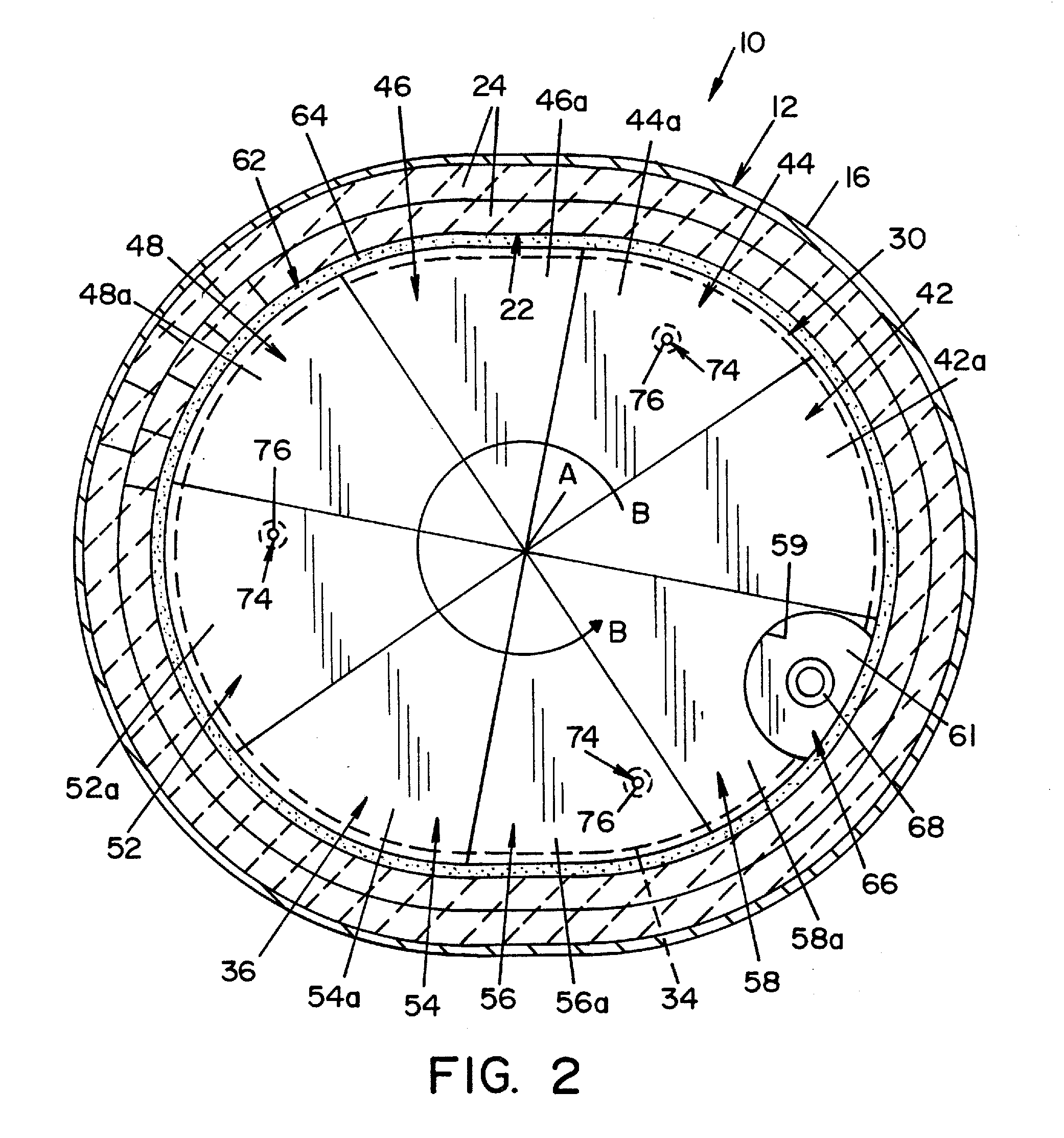
[0044]Referring now to FIGS. 1-3, bottom lining 30, illustrating the present invention, is shown. Bottom lining 30 has an upper portion comprised of discrete sections. In the embodiment shown, the upper portion of bottom lining 30 is comprised of an uppermost section 42, six (6) intermediate sections 44, 46, 48, 52, 54, 56 and a lowermost section 58. Uppermost section 42, intermediate sections 44, 46, 48, 52, 54, 56 and lowermost section 58 are each basically pie-shaped. Uppermost section 42, intermediate sections 44, 46, 48, 52, 54, 56 and lowermost section 58 are arranged such that each section extends from a center point “A,” best seen in FIG. 2. An opening 59 extends through the portion of bottom lining 30 defining lowermost section 58. Uppermost section 42 has an upper surface 42a, intermediate section 44 has an upper surface 44a, intermediate section 46 has an upper surface 46a, and so forth. Surfaces 42a, 44a, 46a, 48a, 52a, 54a, 56a, 58a are each disposed at a discrete eleva...

third embodiment

[0059]Referring now to FIGS. 6-7, a bottom lining 230 illustrating the present invention is shown. As best seen in FIG. 6, bottom lining 230 is generally oblong in shape and has an upper portion comprised of discrete sections. In the embodiment shown, the upper portion of bottom lining 230 is comprised of an uppermost section 242, two (2) intermediate sections 244, 246 and a lowermost section 258. Uppermost section 242, intermediate sections 244, 246 and lowermost section 258 are basically elongated sections that transverse the upper portion of bottom lining 230. Uppermost section 242 has an upper surface 242a and an edge 242b. Intermediate section 244 has an upper surface 244a and an edge 244b. Intermediate section 246 has an upper surface 246a and an edge 246b. Lowermost section 258 has an upper surface 258a. In the embodiment shown, edges 242b, 244b, 246b are parallel to each other. Surfaces 242a, 244a, 246a, 258a are each disposed at a discrete elevation and combine to form an u...

sixth embodiment

[0081]After ladle 10 is filled with a predetermined amount of molten metal, the casting of molten metal using bottom lining 530 in ladle 10 is similar in most respects to casting molten metal using bottom lining 30 in ladle 10. In the sixth embodiment, the slag adheres to surface sections 542, 544, 546, 548, 558. In addition, as molten metal drains from ladle 10, the molten metal above upper surface 536 and beneath the slag layer flows from successive surface sections 542, 544, 546, 548 of stepped portion 540 along a path “J-J” in a counter-clockwise direction.

[0082]Raised curb 592 causes the molten metal above lowermost section 558 and beneath the slag layer to separate and flow along first flow path “H-H” and second flow path “I-I.” According to the present invention, raised curb 592 is dimensioned and positioned such that first flow path “H-H” causes the molten metal to flow in a first direction toward first opening 559 and second flow path “I-I” causes the molten metal to flow i...


PUM

PropertyMeasurementUnit
refractoryaaaaaaaaaa
elevationaaaaaaaaaa
volumeaaaaaaaaaa

Abstract

A refractory bottom lining for lining the bottom of a metallurgical vessel. The refractory bottom includes a stepped portion and an impact portion. The impact portion is formed of a first refractory material. The stepped portion is formed of a second refractory material and is disposed around the impact portion. The stepped portion includes an upper surface that has a plurality of discrete surface sections. The plurality of discrete surface sections includes an uppermost surface section, at least two intermediate surface sections and a lowermost surface section. Each surface section has a different elevation such that the uppermost surface section has a highest elevation and the lowermost surface section has a lowest elevation. The uppermost surface section, the at least two intermediate surface sections and the lowermost surface section define a continuously downward stepped path from the uppermost surface section to the lowermost surface section.

Description

RELATED APPLICATIONS[0001]This application is a continuation-in-part of U.S. application Ser. No. 12 / 032,720, filed Feb. 18, 2008.FIELD OF THE INVENTION[0002]The present invention relates generally to refractory linings for metallurgical vessels, and more particularly to a lining bottom for such vessels. The invention is particularly applicable for use in ladles used in handling molten steel, and will be described with particular reference thereto. It will, of course, be appreciated that the present invention has application in other types of metallurgical vessels for handling molten metal.BACKGROUND OF THE INVENTION[0003]In the manufacture of steel, molten steel is poured from a metallurgical furnace into a ladle. In pouring the liquid metal from the metallurgical furnace, there is typically some carryover of slag from the furnace into the ladle. The molten steel may also undergo further refinement in the ladle. In this respect, various slag-forming constituents may be added to the...

Claims


Application Information

Patent Timeline
Patent Type & Authority Applications(United States)
IPC IPC(8): C21B3/00
CPCB22D41/02F27D1/10F27D1/04F27D1/0043
Inventor BARRETT, RONALDABRINO, DONALD
Owner HARBISONWALKER INT INC
Why Eureka
Try Eureka