Power generating device, electronic apparatus, and transportation apparatus

a technology of power generation device and electronic device, which is applied in the direction of piezoelectric/electrostrictive/magnetostrictive device, piezoelectric/electrostriction/magnetostriction machine, electrical apparatus, etc., can solve the problems of difficult to reduce the size of the power generating device, limited voltage level of acquired voltage, etc., to achieve large amount of electric charge, increase the amount of electric charge generation, and increase the amount of piezoelectri

Active Publication Date: 2012-05-24
SEIKO EPSON CORP
View PDF10 Cites 22 Cited by
  • Summary
  • Abstract
  • Description
  • Claims
  • Application Information

AI Technical Summary

Benefits of technology

[0010]In the above-described power generating device, since the first piezoelectric device and the second piezoelectric device are disposed pn the transformation member, as the transformation member transforms, the first piezoelectric device and the second piezoelectric device transform. As a result, in these piezoelectric devices, positive and negative electric charge is generated based on the piezoelectric effect. In addition, the amount of generation of the electric charge increases as the amount of transformation of the piezoelectric device increases. In addition, the first piezoelectric device configures a resonance circuit together with the inductor, and a switch is disposed in the resonance circuit. When the transformation of the transformation member is started in a state in which the conduction of the switch is cut off, and the amount of transformation has an extreme value (in other words, the direction of the transformation is switched), the switch is allowed to be in the conductive state. The first piezoelectric device (and the second piezoelectric device) is transformed together with the transformation member and generates large amount of electric charge as the amount of transformation increases. Accordingly, when the amount of electric charge generated by the first piezoelectric device (and the second piezoelectric device) is the most, the first piezoelectric device is connected to the inductor so as to form the resonance circuit. Then, the electric charge generated in the first piezoelectric device flow into the inductor. Since the first piezoelectric device and the inductor configures the resonance circuit, the current flowing into the inductor overshoots so as to flow into a terminal disposed on a side opposite to the first piezoelectric device. This period (that is, a period until the electric charge started to flow from one terminal of the first piezoelectric device flows into the first piezoelectric device again from the terminal disposed on the opposite side through the inductor) is a half of the resonance period of the resonance circuit that is formed by the first piezoelectric device and the inductor. Accordingly, when the transformation direction of the first piezoelectric device is switched, the switch is connected so as to form the resonance circuit, and thereafter, when a time of a half the resonance period elapses, the switch is cut off, whereby the arrangement of positive and negative charge generated inside the first piezoelectric device before connection of the inductor can be reversed. From the state, this time, when the transformation member is transformed in the opposite direction, the first piezoelectric device is transformed in the opposite direction, and, from the state in which the arrangement of the positive and negative charge is reversed, new electric charge newly generated based on the piezoelectric effect further increases, and the electric charge is accumulated in the first piezoelectric device. In addition, as the electric charge is accumulated inside the first piezoelectric device, the generated voltage increases. Accordingly, a voltage that is higher than a voltage generated due to electric polarization of a piezoelectric material composing the first piezoelectric device can be generated without separately arranging a booster circuit. Furthermore, in order to efficiently accumulate electric charge inside the first piezoelectric device as above, it is important to connect the switch and form a resonance circuit when the transformation direction of the first piezoelectric device is switched. Here, since the first piezoelectric device and the second piezoelectric device are disposed on the transformation member, when the transformation direction of the first piezoelectric device is switched, the transformation direction of the second piezoelectric device is switched as well. The second piezoelectric device generates a higher voltage as the amount of transformation increases, and the voltage generated by the second piezoelectric device has an extreme value when the transformation direction of the second piezoelectric device is switched. Therefore, the voltage generated in the second piezoelectric device is detected, and the switch is in the conductive state only in a predetermined period from the time point at which the voltage has the extreme value, whereby the electric charge can be efficiently accumulated inside the first piezoelectric device.

Problems solved by technology

However, according to such proposed general techniques, there is a problem that an acquired voltage is limited to the voltage level up to a voltage that is generated in accordance with the electric polarization of the piezoelectric material.
Accordingly, in many cases, a booster circuit is necessary in addition to a power generating circuit that derives electricity from the piezoelectric material, and thus there is a problem that it is difficult to decrease the size of the power generating device.

Method used


Image

  • Power generating device, electronic apparatus, and transportation apparatus
  • Power generating device, electronic apparatus, and transportation apparatus
  • Power generating device, electronic apparatus, and transportation apparatus

Examples


first embodiment

A. First Embodiment

A-1. Structure of Power Generating Device According to First Embodiment

A-2. Operation of Power Generating Device According to First Embodiment

A-3. Principle of Operation of Power Generating Device According to First Embodiment

A-4. Switch Switching Timing According to First Embodiment

B. Second Embodiment

[0025]C. Alternative embodiments

C-1. First Alternative embodiment

C-2. Second Alternative embodiment

C-3. Third Alternative embodiment

A. First Embodiment

A-1. Structure of Power Generating Device According to First Embodiment

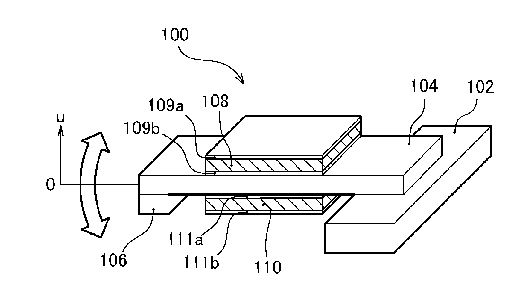
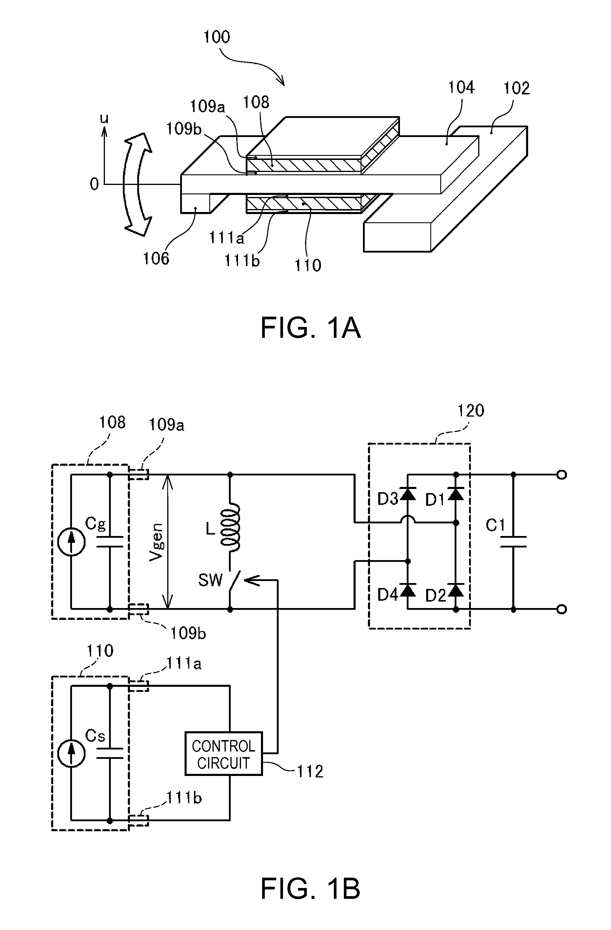
[0026]FIGS. 1A and 1B are explanatory diagrams illustrating the structure of a power generating device 100 according to a first embodiment. FIG. 1A shows the mechanical structure of the power generating device 100, and FIG. 1B shows the electrical configuration thereof. As the mechanical structure of the power generating device 100 according to the first embodiment, a structure is formed in which a crossbeam 104 having a spindle 106 disposed at the...

second embodiment

B. Second Embodiment

[0059]In the power generating device 100 of the first embodiment described above, only one control piezoelectric device 110 is described. However, the number of the control piezoelectric devices 110 is not necessarily limited to one, and a plurality of control piezoelectric devices may be provided. Hereinafter, such a second embodiment will be described. In the second embodiment, the same reference numeral is assigned to each configuration that is the same as that of the first embodiment, and a detailed description thereof will not be presented.

[0060]FIGS. 7A to 7C are explanatory diagrams illustrating a power generating device 100, which includes control piezoelectric devices, according to a second embodiment. FIG. 7A is a plan view viewed from one face of a crossbeam 104. FIG. 7B is a plan view viewed from the other face of the crossbeam 104. In FIG. 7A, a power generation piezoelectric device 108 disposed on one face of the crossbeam 104 is represented. In FIG...

first alternative embodiment

C-1. First Alternative Embodiment

[0069]In the above-described second embodiment, it has been described that two control piezoelectric devices 110 and 114 respectively have a same length as the power generation piezoelectric device 108, and the control piezoelectric devices 110 and 114 are disposed at positions approaching both ends in the widthwise direction of the crossbeam 104. However, two piezoelectric devices 110 and 114 that are respectively shorter than half the length of the power generation piezoelectric device 108 may be arranged so as to be aligned in one row toward the longitudinal direction at the center position of the crossbeam 104.

[0070]FIGS. 8A and 8B are explanatory diagrams illustrating the appearance in which a power generation piezoelectric device 108 and two control piezoelectric devices 110 and 114 are disposed in the crossbeam 104 of the power generating device 100 of the first alternative embodiment. FIG. 8A is a plan view viewed from one face of the crossbe...


PUM


Abstract

A power generating device which includes a transformation member that is transformed by receiving a transformation force in a transformation direction, a first piezoelectric device that is disposed on the transformation member, a second piezoelectric device that is disposed on the transformation member, an inductor comprising a resonance circuit including the first piezoelectric device, a switch that is disposed in the resonance circuit, and a control unit that controls the switch to be in a conductive state for a predetermined period by detecting a voltage generated in the second piezoelectric device as the second piezoelectric device is transformed in response to the transformation force being applied to the transformation member.

Description

CROSS REFERENCES TO RELATED APPLICATIONS[0001]The entire disclosure of Japanese Patent Application No. 2010-257568, filed Nov. 18, 2010 is expressly incorporated herein by reference.BACKGROUND[0002]1. Technical Field[0003]The present invention relates to a power generating device that derives electric energy from electric charge which results when a piezoelectric material such as a piezoelectric device receives an external force.[0004]2. Related Art[0005]When a piezoelectric material such as lead zirconate titanate (PZT), crystal (SiO2), or zinc oxide (ZnO) has an external force applied thereto, electric polarization is caused inside the material, and positive and negative electric charge appears on the surface. Such a phenomenon is called a piezoelectric effect. A method of generating power is proposed in which, by using such a property of the piezoelectric material, a cantilever is vibrated so as to repeatedly weight the piezoelectric material, and electric charge generated on the...

Claims


Application Information

Patent Timeline
Patent Type & Authority Applications(United States)
IPC IPC(8): H02N2/18
CPCH02N2/188H02N2/181H02N2/186H10N30/306
Inventor TABATA, KUNIOOSHIMA, ATSUSHIYOSHINO, HIROYUKIIDE, NORITAKAHIRABAYASHI, ATSUYA
Owner SEIKO EPSON CORP
Why Eureka
Try Eureka