
Battery charger having non-contact electrical switch

Inactive Publication Date: 2012-05-24
DELPHI TECH INC
View PDF26 Cites 63 Cited by
  • Summary
  • Abstract
  • Description
  • Claims
  • Application Information

AI Technical Summary

Benefits of technology

[0007]In a further aspect of the invention, the non-contact electrical switc

Problems solved by technology

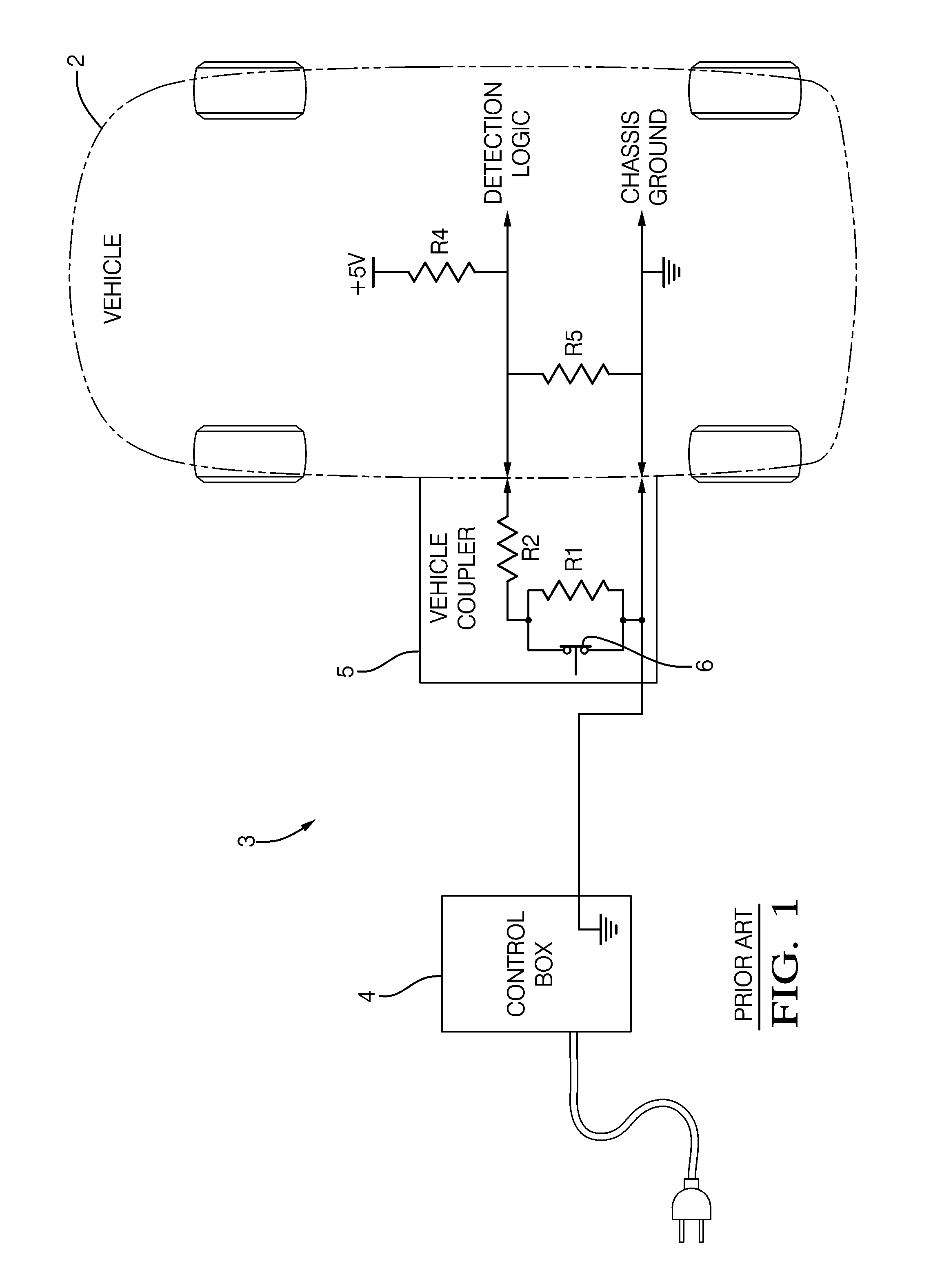
The contacts (not shown) of the mechanical switch (6) are subject to wear and may actually wear out with repeated use of the mechanical switch (6) that may lead to a decreased product life and require early undesired servicing of the mechanical switch (6).
Additionally, a potentially unsafe situation may develop if the vehicle coupler (5) is disconnected from the vehicle (2) by an operator of the system (3) while the battery is simultaneously being electrically charged, otherwise known as a hot disconnect of the vehicle coupler (5).

Method used


Image

  • Battery charger having non-contact electrical switch
  • Battery charger having non-contact electrical switch
  • Battery charger having non-contact electrical switch

Examples


Embodiment Construction

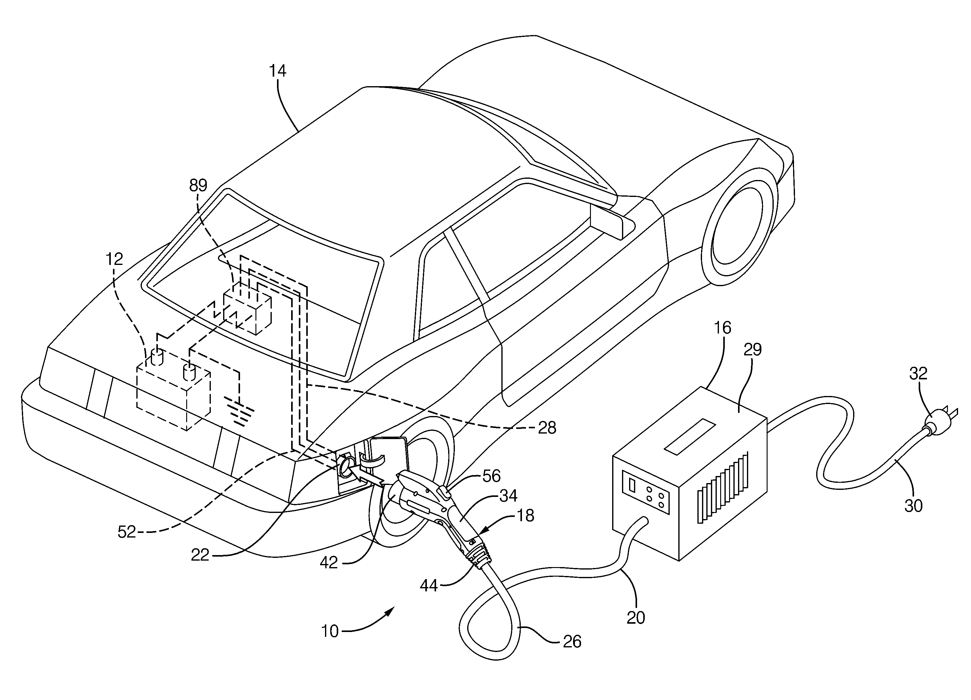
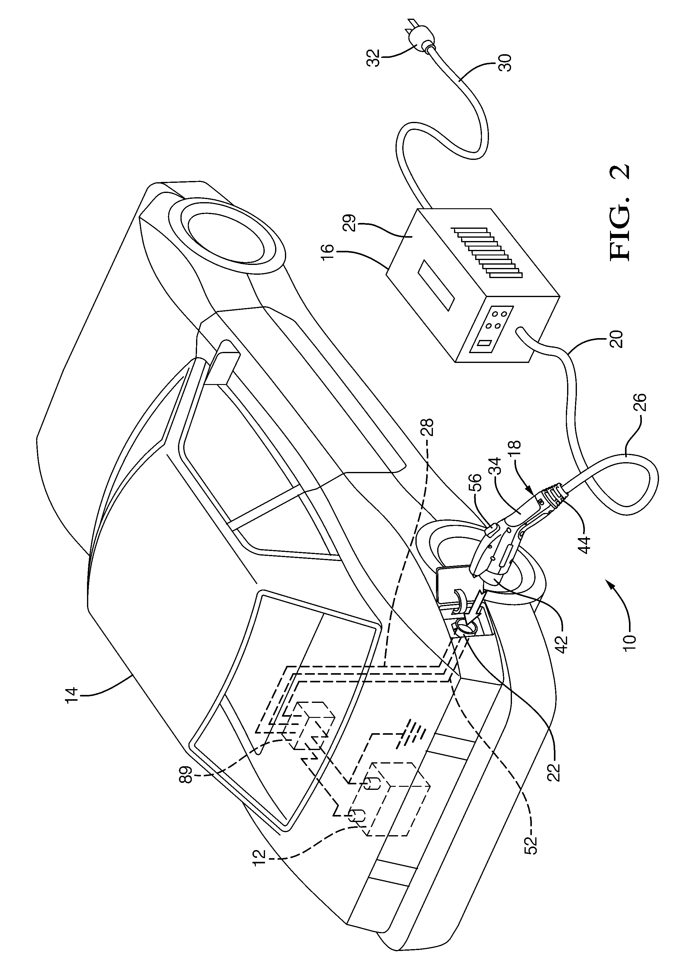
[0021]A drivetrain of a vehicle is a group of components in the vehicle that generate power and deliver this power through the wheels of the vehicle to a road surface. A hybrid electric vehicle and an electrical vehicle each use a battery to power the drivetrain of their respective vehicles. A hybrid electrical vehicle uses a hydrocarbon fuel engine in combination with a battery disposed on the vehicle to power the drivetrain of a vehicle. An electric vehicle powers the drivetrain solely by using energy from a battery. The battery of the hybrid electric vehicle and the electric vehicle may include a plurality of batteries connected in series or parallel connection to form a single battery. As the vehicle is driven, or otherwise used by a human operator of the vehicle such as when powering the radio or windshield wipers apart from powering the drivetrain, the electrical charge on the battery may decrease such that the battery needs to be electrically recharged back to a fully charged...


PUM


Abstract

The handle of a charge coupler includes a mechanical latch that securely mechanically locks the handle to the vehicle passively when the handle is manually attached to the vehicle by a human operator to create an electrical connection between the vehicle and the charger. The handle also has an actuator movable by the operator from a deactivated state to a first and a second position activated state. The mechanical latch operates independently of the state of the actuator when the handle is being manually attached but being mechanically released by the actuator when it is moved to its second activated state. A non-contact electrical switch means associated with the actuator breaks the electrical connection when the actuator is moved to the first position activated state before releasing the mechanical latch at said second activated position.

Description

TECHNICAL FIELD[0001]This invention is directed to a battery charger for a vehicle, more particularly, a charge coupler includes a handle in electrical communication with the charger and provisions in the handle electrically manage an electrical connection state with the vehicle independent from a mechanical connection state with the vehicle.BACKGROUND OF INVENTION[0002]It is known, referring to FIG. 1, to electrically charge a battery of an electric vehicle (2) using a battery charging system (3) that is connected to the vehicle (2). The charging system (3) includes a control box (4) connected to a vehicle coupler (5). The vehicle coupler (5) is attached to the vehicle (2) to charge the battery. The vehicle coupler includes a mechanical switch (6). When the mechanical switch (6) is closed, an electrical output changes state so that the vehicle (2) senses the presence of the vehicle coupler (5) and enables charging of the battery by the system (3). When a latch mechanism (not shown)...

Claims


Application Information

Patent Timeline
IPC IPC(8): H02J7/00
CPCB60L3/0069B60L11/1818B60L11/1846B60L2230/12B60L2230/16B60L2240/36Y04S30/14Y02T10/7088Y02T90/121Y02T90/128Y02T90/14Y02T90/163Y02T90/169Y02T10/7005B60L53/16B60L53/65B60L53/18B60L53/305Y02T10/7072Y02T90/12Y02T90/167Y02T90/16Y02T10/70
Inventor KIKO, JEFFREY S.SENK, JOSEPH MATTHEWPASHA, BRIAN D.MARZO, STEVEN WILLIAM
Owner DELPHI TECH INC
Learn More