
Method and apparatus for magnetic response imaging

a technology of magnetic response and imaging method, which is applied in the direction of instruments, electrical/magnetic thickness measurements, magnetic property measurements, etc., can solve the problems of difficult detection of small changes in conductivity of metals, and inability to monitor continuous pipelines. , to achieve the effect of stable measurement and detection of small levels of corrosion and deterioration

Inactive Publication Date: 2012-05-24
4D IMAGING
View PDF2 Cites 10 Cited by
  • Summary
  • Abstract
  • Description
  • Claims
  • Application Information

AI Technical Summary

Benefits of technology

[0019]The present invention relates to apparatus and methods which can be utilized for identifying, measuring, and monitoring metal loss through corrosion or other deleterious factors in metallic materials and especially in ferromagnetic piping and ferromagnetic vessels. The excitation and response signals can penetrate insulating materials and non-ferromagnetic metallic coverings of the piping and vessels. That provides an important advantage for use in existing pipelines which usually have such coverings in place. Computer monitoring of pipelines for metal loss over an extended period of time, e.g., months or years, is important for the determination of the safety and integrity of the pipe. The system is designed to provide very stable measurements in order to detect small levels of corrosion and deterioration.

Problems solved by technology

In practice, it is difficult to detect the small changes in conductivity of a metal as it corrodes, since the effects of the corrosion will generally be very small compared to the remaining metal.
It is not practicable for continuous monitoring of a pipeline for corrosion because the system stability of the transmission line is not sensitive to small levels of corrosion.

Method used


Image

  • Method and apparatus for magnetic response imaging
  • Method and apparatus for magnetic response imaging
  • Method and apparatus for magnetic response imaging

Examples


Embodiment Construction

[0028]The present invention generally comprises apparatus and methods which can be utilized for identifying, measuring, and monitoring metal loss through corrosion or other deleterious factors in metallic materials and especially in ferromagnetic piping and ferromagnetic vessels.

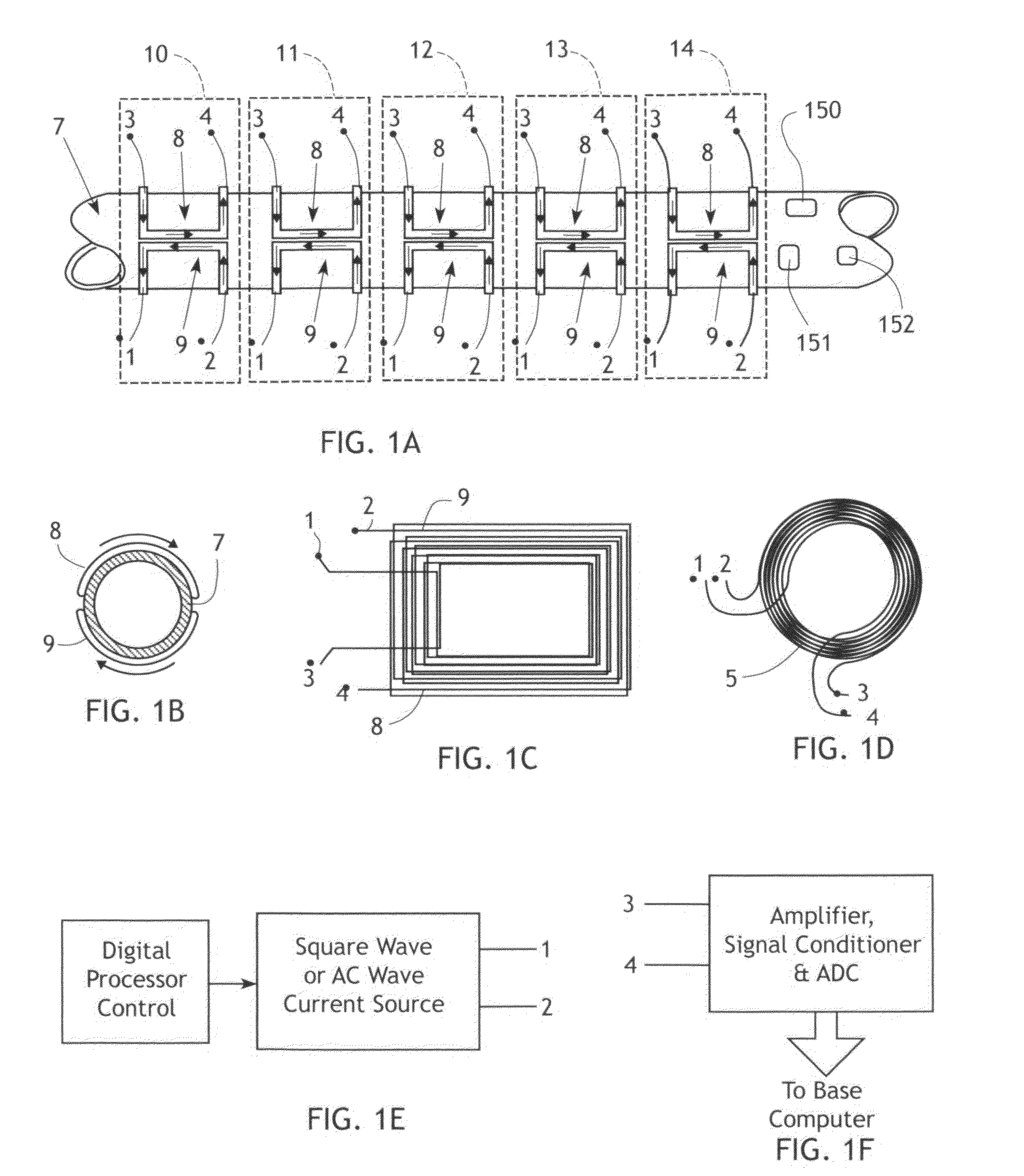
[0029]FIG. 5 depicts a set of coils, each with a driver coil and a receiver coil either wound together or close by, as shown in FIG. 1D, mounted circumferentially about a section of a pipeline 7. The heavier coils D (shown in darker line), have ends 51 and 52 that are connected to be driven by a signal source to generate an electromagnetic field. The coils are multiplexed so that they may be driven individually or in groups, as described below. The lighter coils R (shown in fine line) have ends 53 and 54 and are the receiving coils which generate a response signal stimulated by the electromagnetic signal transferred by the magnetic domains of the pipeline sidewall.

[0030]The AC or fluctuating current from the...


PUM


Abstract

An apparatus and method for identifying, measuring, and monitoring metal loss through corrosion or other deleterious factors in ferromagnetic piping and ferromagnetic objects. Drive coils secured to the object are driven to emit a magnetic field which is transmitted through the object by magnetic domains in the object. Response coils detect the magnetic domains and generate a response signal. The drive and response signals can penetrate insulating materials and non-ferromagnetic metallic coverings of the piping and vessels. The system operates reiteratively over an extended period of time, e.g., months or years, to detect loss of magnetic domains which is an important indicator of corrosion and deterioration of the object.

Description

CROSS-REFERENCE TO RELATED APPLICATIONS[0001]Not applicable.FEDERALLY SPONSORED RESEARCH[0002]Not applicable.SEQUENCE LISTING, ETC ON CD[0003]Not applicable.BACKGROUND OF THE INVENTION[0004]1. Field of the Invention[0005]The present invention relates to apparatus and methods which can be utilized for identifying, measuring, and monitoring metal loss through corrosion or other deleterious factors in metallic materials and especially in ferromagnetic piping and ferromagnetic vessels.[0006]2. Description of Related Art[0007]The following patents and publications exemplify the state of the art in systems for detecting corrosion in metallic systems, particularly pipes and pipelines.[0008]Patent Publication No. US2002 / 0153249 by Eric Atherton describes a metallic corrosion monitoring system which employs the measurement of electrical current flow in the metal. This method is not as sensitive as the present invention and its measurement of magnetic flux for the detection of corrosion. Ther...

Claims


Application Information

Patent Timeline
Patent Type & Authority Applications(United States)
IPC IPC(8): G01R33/12G01B7/06
CPCG01N17/006G01R33/1223G01N27/87
Inventor RONDINONE, DAVIDSINGER, JEROME R.STEVICK, GLENZALABAK, JOHN
Owner 4D IMAGING
Learn More