System and method for monitoring birefringent particles in a fluid

a technology of imaging system and birefringent particle, applied in the field of optical flow imaging and analysis configuration, can solve the problems of inconclusive counts, inability to easily automate, and tedious microscope methods, so as to improve the ability to easily monitor, improve the accuracy and sensitivity of birefringent particle monitoring, and improve the accuracy of individual organism counts.

Active Publication Date: 2012-05-24
YOKOGAWA FLUID IMAGING TECH INC
View PDF2 Cites 32 Cited by
  • Summary
  • Abstract
  • Description
  • Claims
  • Application Information

AI Technical Summary

Benefits of technology

[0010]The system and related method of the present invention enhances the accuracy and sensitivity of birefringent particle monitoring including, but not limited to, minerals, pharmaceuticals, emulsions, crystals (including crystalline organic structures such as Zebra Mussels) and fibers monitoring, by utilizing imaging systems combined with birefringent particle analysis.
[0011]The advantages gained by the invention compared to the state of the art of currently available methods are: 1) more accurate measurements of individual organism counts from scatter signals and birefringence imaging; and 2) better ability to easily monitor for such particles versus conventional manual microscope techniques. In the two LED / two camera embodiment of the invention the infrared LED penetrates the shells of the veligers and allows imaging of internal features that would not be possible with strictly visible illumination. The red illumination provides sharper imaging of the external features than would be possible with infrared imaging. Therefore, when used together, the two LEDs result in veliger images with sharp external features and visible internal features. These and other advantages of the present invention will become more readily apparent upon review of the following detailed description and the accompanying drawings.

Problems solved by technology

The inefficiencies of manually counting particles with a microscope may result in inconclusive counts based on the less than optimum collection of water samples from a pond or lake sample.
This microscope method is also tedious and time consuming.
It also does not lend itself to easy automation.

Method used


Image

  • System and method for monitoring birefringent particles in a fluid
  • System and method for monitoring birefringent particles in a fluid
  • System and method for monitoring birefringent particles in a fluid

Examples


second embodiment

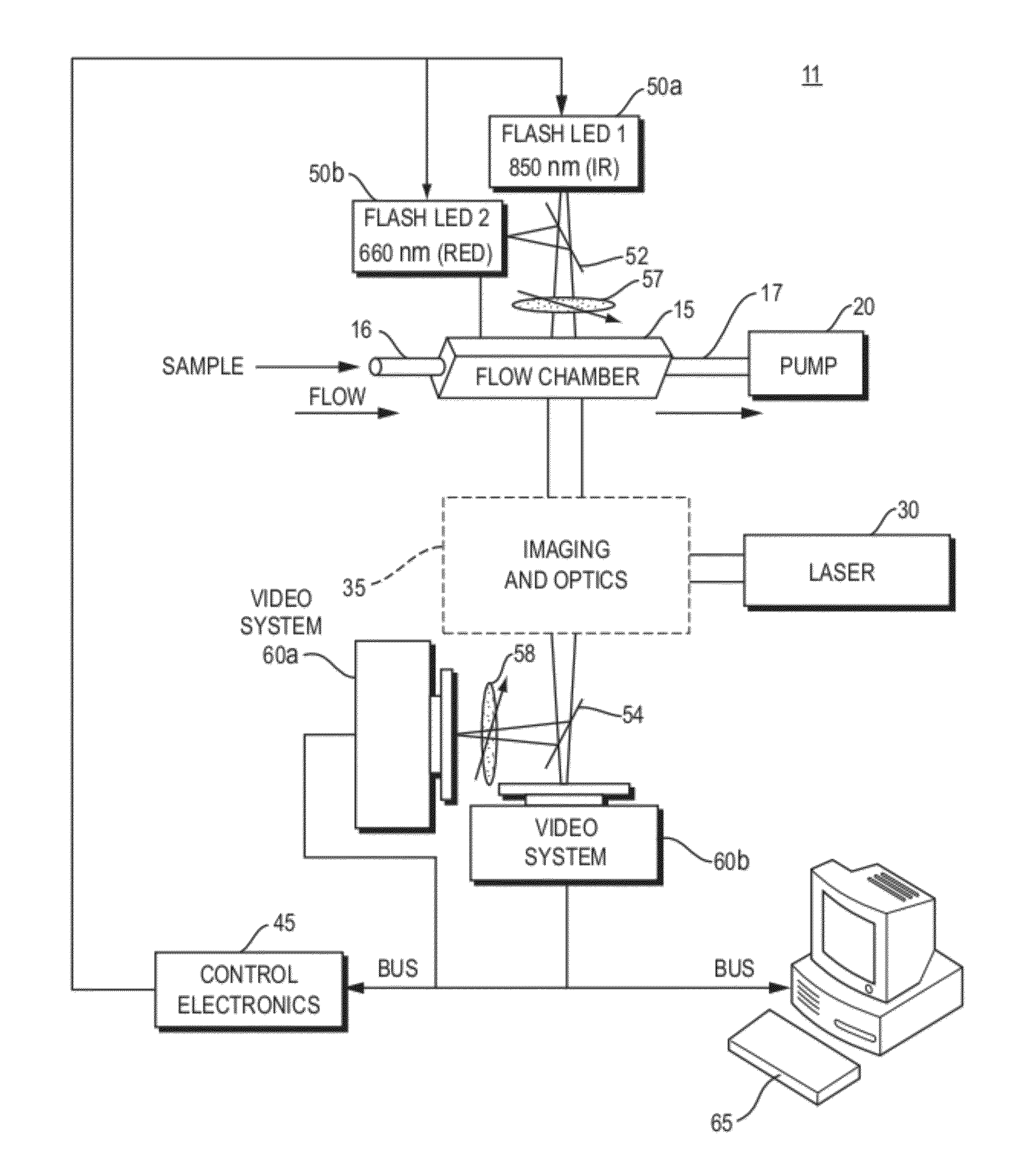
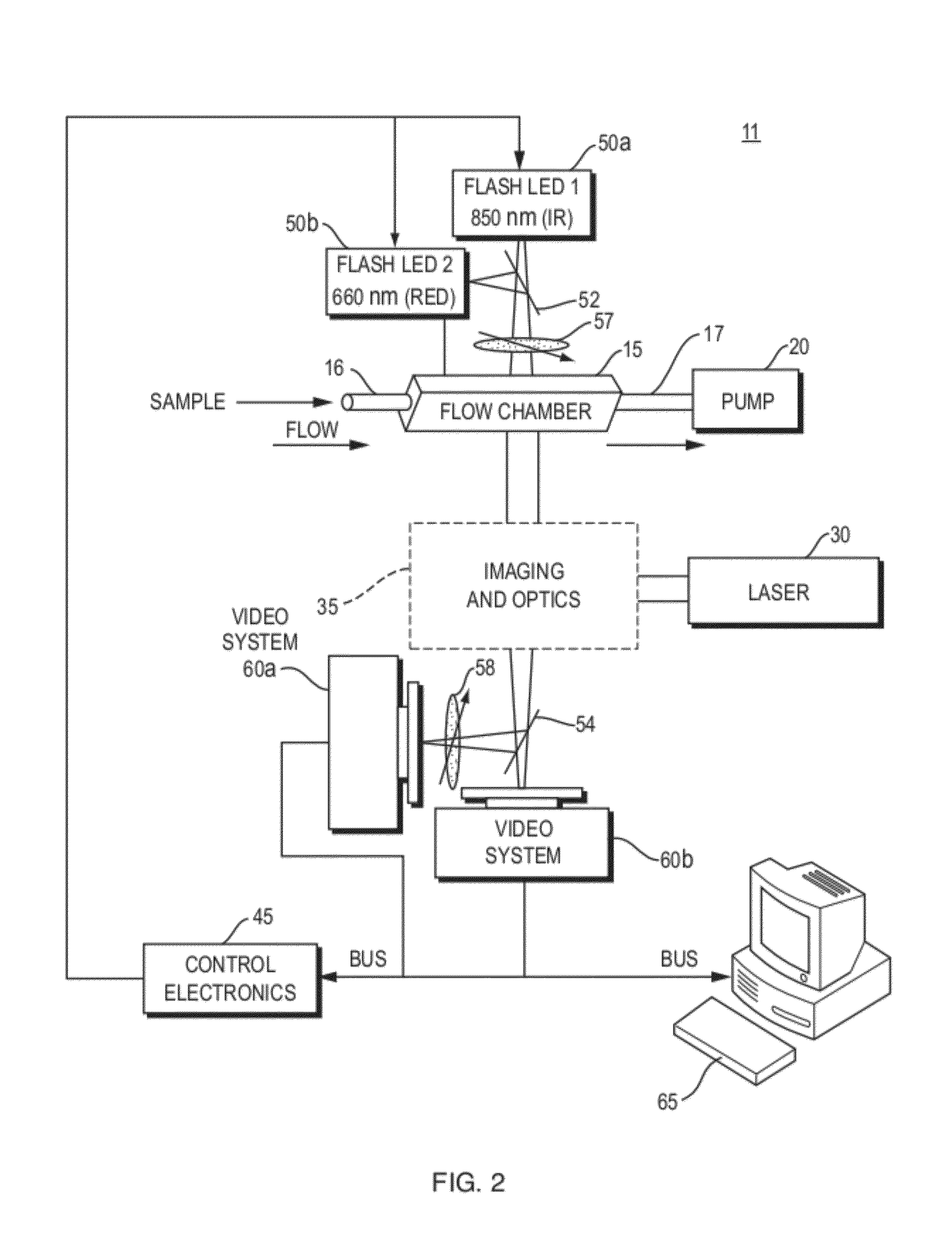
[0026]In the invention identified as system 11 and represented in FIGS. 2 and 5, the control electronics 45 and the computing device 65 are arranged to activate backlighting from a combination of two LEDs, a first LED 50a and a second LED 50b. In this system 11, the first LED 50a is a 10 mm 3 chip 15 degree 200 mw 850 nm (infrared, “IR”) LED. The second LED 50b is a 10 mm red 660 nm LED mounted next to the first LED 50a. The second LED 50b is configured to reflect off a 700 nm long pass filter 52, such as an Edmunds 47-260 filter.

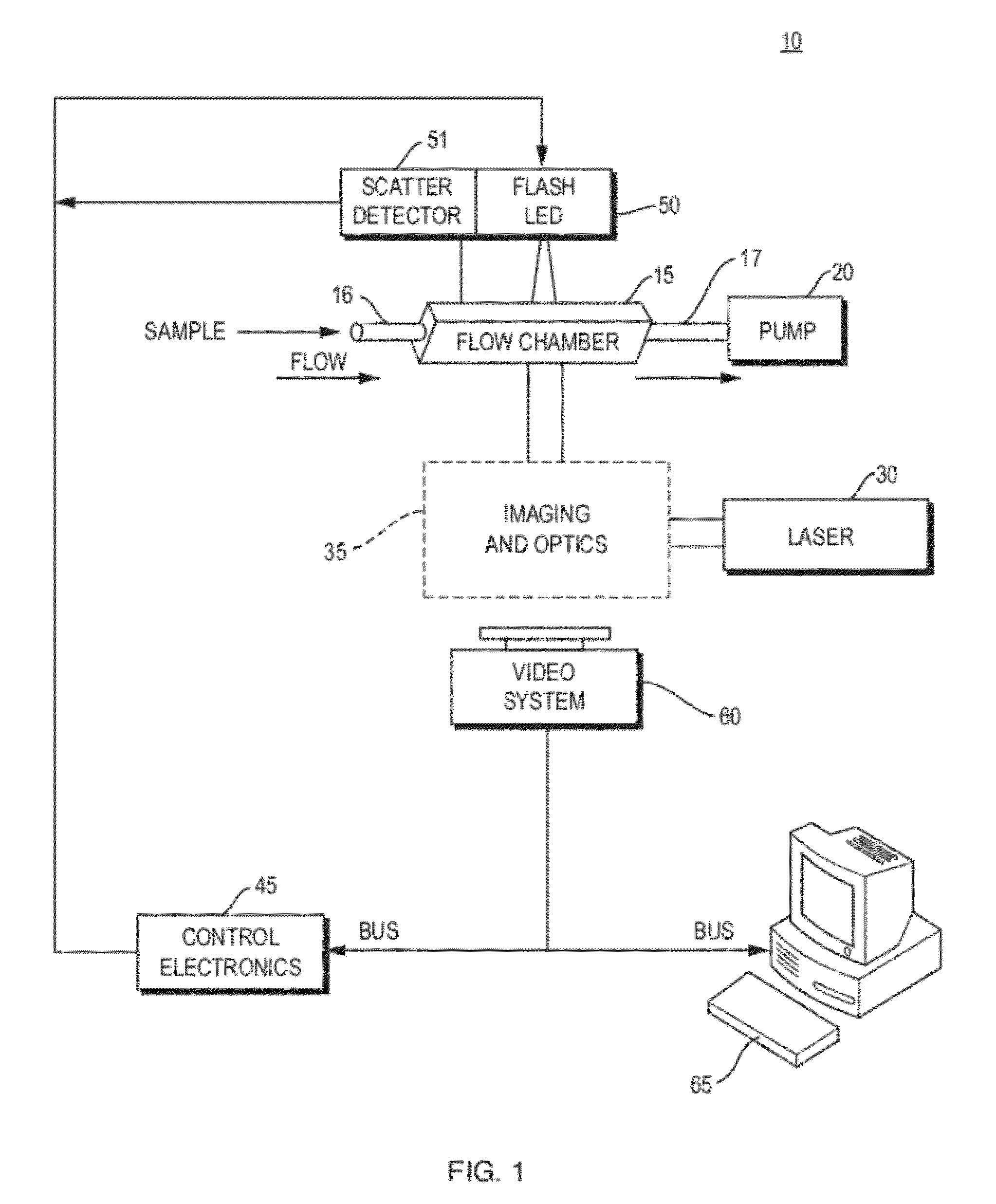
[0027]In both embodiments of the invention, the polarization analyzers 57 and 58 are crossed, meaning that under normal conditions, light filtered by analyzer 57 is polarized perpendicular to the polarization axis of analyzer 58 so little or no light can pass through 57 and then through 58. The polarization analyzers 57 and 58 only allow light to reach the image capturing system 60 if it passes through particles, that is, birefringent particles, and has its...

first embodiment

[0028]The image capturing system 60 is arranged to either retain the captured image, transfer it to the computing device 65, or a combination of the two. In the first embodiment, the image capturing system 60 includes characteristics of a digital camera or an analog camera with a framegrabber or other means for retaining images. For example, but in no way limiting what this particular component of the system may be, the image capturing system 60 may be, but is not limited to being, a CCD firewire, a CCD USB-based camera, or other suitable device that can be used to capture images and that further preferably includes computing means or means that may be coupled to computing means for the purpose of retaining images and to manipulate those images as desired. The computing device 65 may be programmed to measure the size and shape of the particle captured by the image capturing system 60 and / or store the data for later analysis.

[0029]In the second embodiment, the image capturing system ...


PUM


Abstract

An imaging system with an imaging mechanism which includes polarization analyzers, which may be crossed polarization analyzers, positioned to provide birefringence images of particles in the fluid passing through the flow chamber. Captured images are of high resolution and may be used in comparison to known images of a library of images. The system and related method enhance the accuracy and sensitivity of particle monitoring by utilizing birefringence imaging combined with particle analysis and the detection of each particle's characteristic features, such as crystalline features. The system includes a scatter detector used to trigger backlighting of the flow chamber and capture images of particles therein.

Description

CROSS REFERENCE TO RELATED APPLICATIONS[0001]The present relates to, and claims the priority benefit of, U.S. Provisional Patent Application No. 61 / 086,010, filed Aug. 4, 2008, entitled SYSTEM AND METHOD FOR MONITORING ZEBRA MUSSELS IN A FLUID, of the same named inventors, and U.S. Nonprovisional patent application Ser. No. 12 / 535,536, filed Aug. 4, 2009, entitled SYSTEM AND METHOD FOR MONITORING BIREFRINGENT PARTICLES IN A FLUID, assigned to a common assignee. The entire content of those applications is incorporated herein by reference.BACKGROUND OF THE INVENTION[0002]1. Field of the Invention[0003]The present invention relates generally to an optical flow imaging and analysis configuration used in particle analysis instrumentation, and more particularly to a birefringent particle in-flow imaging system configured to enable the accurate identification of particles in a fluid.[0004]2. Description of the Prior Art[0005]The art has seen various optical / flow systems employed for transp...

Claims


Application Information

Patent Timeline
Patent Type & Authority Applications(United States)
IPC IPC(8): H04N7/18
CPCG01N21/05G01N21/23G02B21/365G01N2201/0627G01N2201/06153
Inventor SIERACKI, CHRISTIAN K.NELSON, WILLIAM H.GRIMM, ROBERT M.ELLIS, SCOTT
Owner YOKOGAWA FLUID IMAGING TECH INC
Why Eureka
Try Eureka