Method for the Automatic Control of Wheel Brake-Slip and Wheel Brake-Slip Control System for a Motor Vehicle With an Electric Drive

a technology of automatic control and control system, which is applied in the direction of braking components, field or armature current control, program control, etc., can solve the adverse effect of vehicle movement dynamics control system on vehicle driving behavior stability, inability to keep a wheel slip in a stable range, and inability to set a friction brake sufficiently to achieve a coefficient of friction of the road, etc., to achieve advantageously reduce the wear of the brake lining, improve the stability of the vehicle, and improve the effect of stability

Active Publication Date: 2012-05-24
CONTINENTAL AUTOMOTIVE GMBH
View PDF12 Cites 20 Cited by
  • Summary
  • Abstract
  • Description
  • Claims
  • Application Information

AI Technical Summary

Benefits of technology

[0009]The method according to the invention for performing closed-loop control of a wheel brake slip comprises the idea that when a vehicle movement dynamics control system becomes active, it is carried out not only by means of a friction brake but also with the aid of torque generated by the electric drive. The electric drive signals and friction brake signals which are generated by means of the slip control device correspond here, in particular, to setpoint values or target values. The electric drive generates an electric drive torque which can be positive or negative, wherein the electric drive comprises an electric motor. A positive electric drive torque causes the wheel to be driven. A negative electric drive torque causes the wheel to be braked. In the latter case, the electric motor is operated as a generator. A negative electric drive torque is also referred to below as a generator-type (regenerative) braking torque. The overall braking torque which is required for slip control is therefore obtained as the sum of the electric drive torque and of the friction braking torque, wherein the changes in torque which are fast but relatively small in amplitude are generated by the electric drive, and the remaining braking torques are generated by the friction brake. In particular, the friction brake generates a basic braking torque onto which the electric drive torque is applied and modulated. In the braking method according to the invention, a slip control is therefore carried out by means of the friction brake and the electric drive, for which reason the slip control can also be referred to as a cooperative slip control.
[0010]The advantages of this cooperative slip control arise, in particular, by virtue of the fact that the electric drive can quickly change its generated electric drive torque, and this torque which can be controlled quickly but is limited in magnitude ideally supplements the braking torque of the friction brake which can be controlled more slowly but is larger in absolute value. As a result, the vehicle movement dynamics control can be advantageously set to quickly changing vehicle situations, in particular if a coefficient of friction of the road changes.
[0011]If a vehicle with an electric drive is mentioned below, this is also intended to include electric drives which have more than one electric motor. In particular, one electric motor may be provided per wheel of a vehicle. That is to say each wheel can be driven or braked individually by means of an electric motor. However, it is also possible to provide that the vehicle has just one electric motor per axle, wherein driving or braking of the wheels takes place here in particular by means of a differential gear mechanism. In particular, in the latter case the torques which are required to perform slip control of the two wheels of the axle is divided into a common highly dynamic component, which is generated by means of the electric motor, and into two further wheel-specific components which are generated by means of the respective friction brakes of the wheels. The vehicle axle can also have, for example, double wheels. Furthermore, the vehicle can comprise not only an electric drive but also, for example, additionally comprise a gasoline engine or a diesel engine. Such vehicles are usually also referred to as hybrid vehicles.
[0012]According to one advantageous refinement of the invention it is possible to provide that an electric drive speed signal is measured and evaluated by means of an evaluation device which is connected to the slip control device. For example, the evaluation device can also be integrated into the slip control device. An electric drive speed signal can be generated, in particular, by means of an electric motor angle sensor (or shaft encoder), for example an electric motor position sensor, which is arranged, for example, in the electric motor for an internal magnetic field control. An electric motor speed which corresponds to a wheel speed of the wheel which is connected to the electric motor can therefore be advantageously measured more quickly and more precisely than in conventional slip control systems.
[0013]It can preferably be provided that a highly dynamic control process of the electric drive torque is carried out at least partially in the electric drive control device. The electric drive control device detects and evaluates, in particular, an electric drive speed. In particular, the electric drive control device comprises a magnetic field control for the electric motor. It is therefore advantageously made possible for the highly dynamic control of the braking effect of the electric motor to take place entirely or partially in the same electronic control device as the motor speed evaluation for the magnetic field control of the electric motor.
[0014]In another preferred embodiment of the invention, a friction brake torque is set to a smaller value than an electric drive torque if a generator-type braking torque which can be generated by means of the electric drive torque is greater than a braking torque which can be applied to a roadway. In such a driving situation, the generator-type braking effect alone is sufficient to perform closed-loop adjustment of the wheel to an optimum brake slip. In particular, under certain circumstances it is even possible here to dispense with activation of the friction brake, i.e. for the friction braking torque to be equal to 0. The friction brake therefore does not have to be activated. As a result, brake lining wear can be advantageously considerably reduced. Fine dust emissions and CO2 emissions are therefore also clearly reduced. The distance or an air gap between a brake caliper and a brake disc of the friction brake is preferably set to zero. This means that the brake caliper on the brake disc slips to just such an extent that no friction braking effect is achieved. The friction brake is to this extent not in its position of rest. This has, in particular, the advantage that the friction brake can be activated directly and without a delay, for example if the coefficient of friction of the road changes.

Problems solved by technology

Although a friction brake can generate a high friction braking torque, the friction brake does not have sufficient dynamics to be able to set itself to a coefficient of friction of the road which changes quickly or suddenly.
However, this means that the vehicle movement dynamics control system can no longer keep a wheel slip in a stable range.
This has an adverse effect on the stability of the vehicle with respect to the driving behavior.
That is to say the vehicle can, under certain circumstances, become dynamically unstable.
A further disadvantage is that the activation of the friction brake results in increased abrasion, which results in an increased quantity of fine friction material dust.
This means that the brake caliper on the brake disc slips to just such an extent that no friction braking effect is achieved.

Method used


Image

  • Method for the Automatic Control of Wheel Brake-Slip and Wheel Brake-Slip Control System for a Motor Vehicle With an Electric Drive
  • Method for the Automatic Control of Wheel Brake-Slip and Wheel Brake-Slip Control System for a Motor Vehicle With an Electric Drive
  • Method for the Automatic Control of Wheel Brake-Slip and Wheel Brake-Slip Control System for a Motor Vehicle With an Electric Drive

Examples


Embodiment Construction

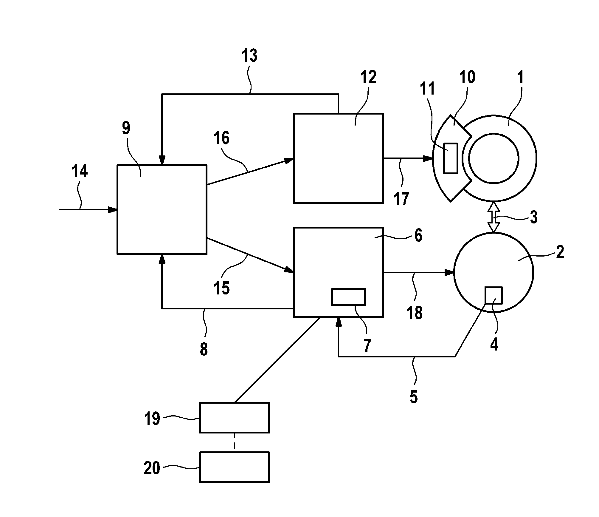
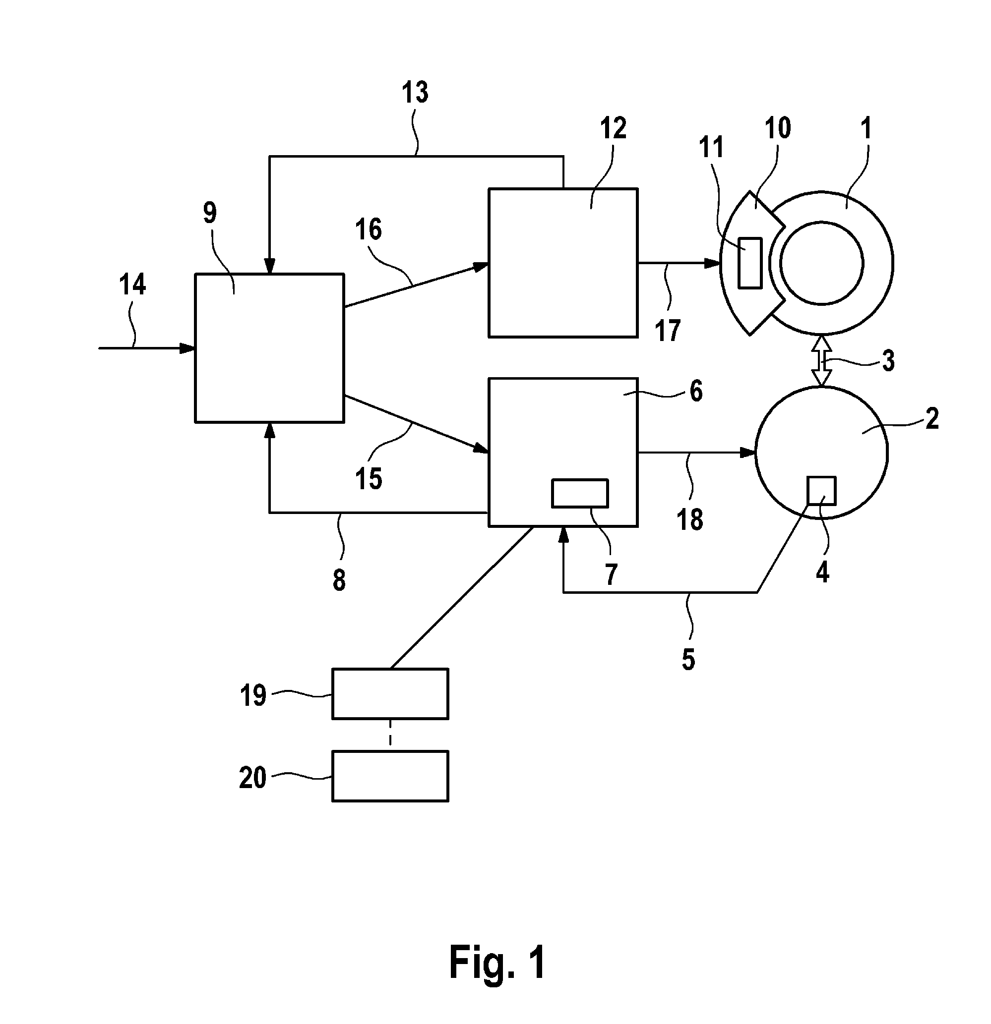
[0020]According to FIG. 1, a wheel 1 of a vehicle (not shown) is connected to an electric drive 2 by means of a mechanical connection 3. The vehicle can be, for example, a passenger car, a truck or a motor cycle. The electric drive 2 comprises an electric motor (not shown). In another exemplary embodiment of the invention which is not shown, the electric drive 2 can also comprise a plurality of electric motors, with the result that each wheel of the vehicle can be driven or braked individually by means of an electric drive. In a further embodiment of the invention which is not shown, the electric motor 2 drives an axle of the vehicle via a differential gear mechanism. In particular, the axle can comprise double wheels.

[0021]The electric drive 2 can either drive the wheel 1 or, if the electric motor is operated as a generator, can generate a generator-type braking torque, with the result that the wheel is braked. The electric drive 2 also comprises an electric motor angle (or angular...


PUM


Abstract

The invention relates to a system and method for the automatic control of wheel brake-slip in a motor vehicle with an electric drive (2), including the following steps: detecting a brake signal (14) by means of a slip control device (9), at which point the slip control device (9) generates an electric drive signal (15) and a friction brake signal (16) for the automatic control of a predetermined slip value of a wheel (1) of the motor vehicle, transmitting the electric drive signal (15) to an electric drive control device (6) and transmitting the friction brake signal (16) to a friction brake control device (12), at which point a friction brake control device (12) activates a friction brake (10) of the wheel (1) according to the friction brake control signal (16) to generate friction brake signal (16) to generate friction brake torque and an electric drive control device (6) activates electric drive (2) according to electric drive signal (15) to generate electric drive torque. The invention further relates to a wheel brake-slip control system for a motor vehicle with an electric drive and to a computer program which are capable of implementing the above described method.

Description

CROSS REFERENCE TO RELATED APPLICATIONS[0001]This application claims priority to German Patent Application Nos. 10 2009 036 250.9, filed Aug. 5, 2009, 10 2010 003 076.7, filed Mar. 19, 2010, and PCT / EP2010 / 059890, filed Jul. 9, 2010.FIELD OF THE INVENTION[0002]The invention relates to a method for performing closed-loop control of a wheel brake slip and to a wheel brake slip control system for a motor vehicle having an electric drive and operated by a computer program.BACKGROUND AND SUMMARY OF THE INVENTION[0003]It is known that vehicles having an electric drive which has an electric motor can be braked in a generator mode (which may include a so-called regenerative mode). During the generator-type braking, the electric motor is operated as a brake by operating the electric motor as a generator.[0004]It is also known that this generator-type braking is switched off as soon as the vehicle movement dynamics control system becomes active. For example, the vehicle movement dynamics cont...

Claims


Application Information

Patent Timeline
Patent Type & Authority Applications(United States)
IPC IPC(8): B60T8/17
CPCB60T2270/602B60T2270/613Y10T477/26B60T8/17555B60T8/1755
Inventor SEMSEY, KOSDORICHT, MICHAEL
Owner CONTINENTAL AUTOMOTIVE GMBH
Why Eureka
Try Eureka