Additive layer fabrication method

a technology of additive layer and fabrication method, which is applied in the direction of manufacturing tools, welding/cutting media/materials, manufacturing tools, etc., can solve the problem that the method does not lend itself to the production of near-network-shape components to close tolerances, and achieve the effects of reducing distortion, reducing distortion in the substrate, and reducing distortion

Inactive Publication Date: 2012-05-31
BAE SYSTEMS PLC
View PDF17 Cites 15 Cited by
  • Summary
  • Abstract
  • Description
  • Claims
  • Application Information

AI Technical Summary

Benefits of technology

[0014]We have found that the distortion can be reduced if the layers nearest the substrate are formed more thickly that those further from it, so that fewer traverses of the laser are needed to establish a foundation for the fabricated structure. This reduces the number of times the substrate is heated to an extent which gives rise to the distortion. Accordingly, when the at least one previously formed layer is adjacent or close to the substrate, it may be formed to be thicker than the at least one further layer, whereby to reduce distortio...

Problems solved by technology

The method does not however lend itself to the production of near-net-...

Method used


Image

  • Additive layer fabrication method
  • Additive layer fabrication method
  • Additive layer fabrication method

Examples


Embodiment Construction

[0019]The invention will now be described merely by way of example with reference to the accompanying drawings, wherein

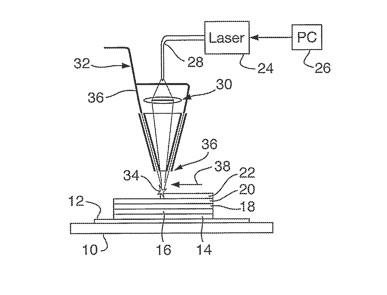
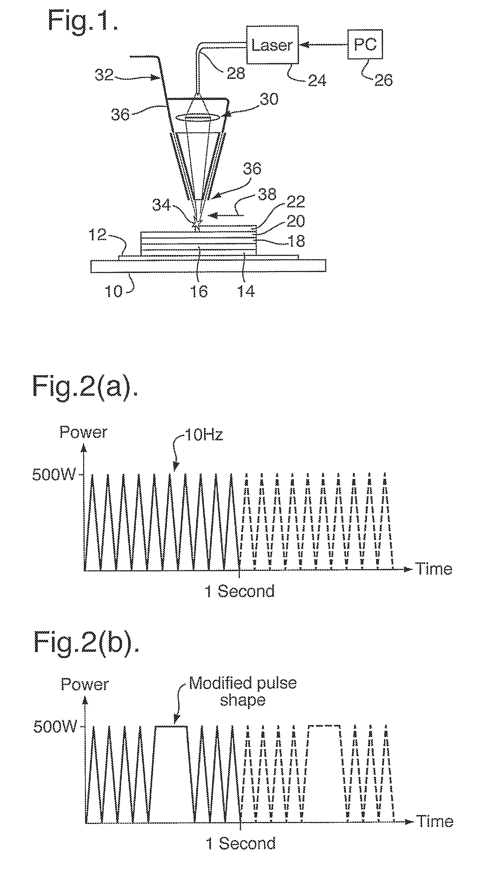
[0020]FIG. 1 shows an apparatus for implementing the method of the invention,

[0021]FIG. 2 shows waveforms of a laser beam produced in the apparatus of FIG. 1;

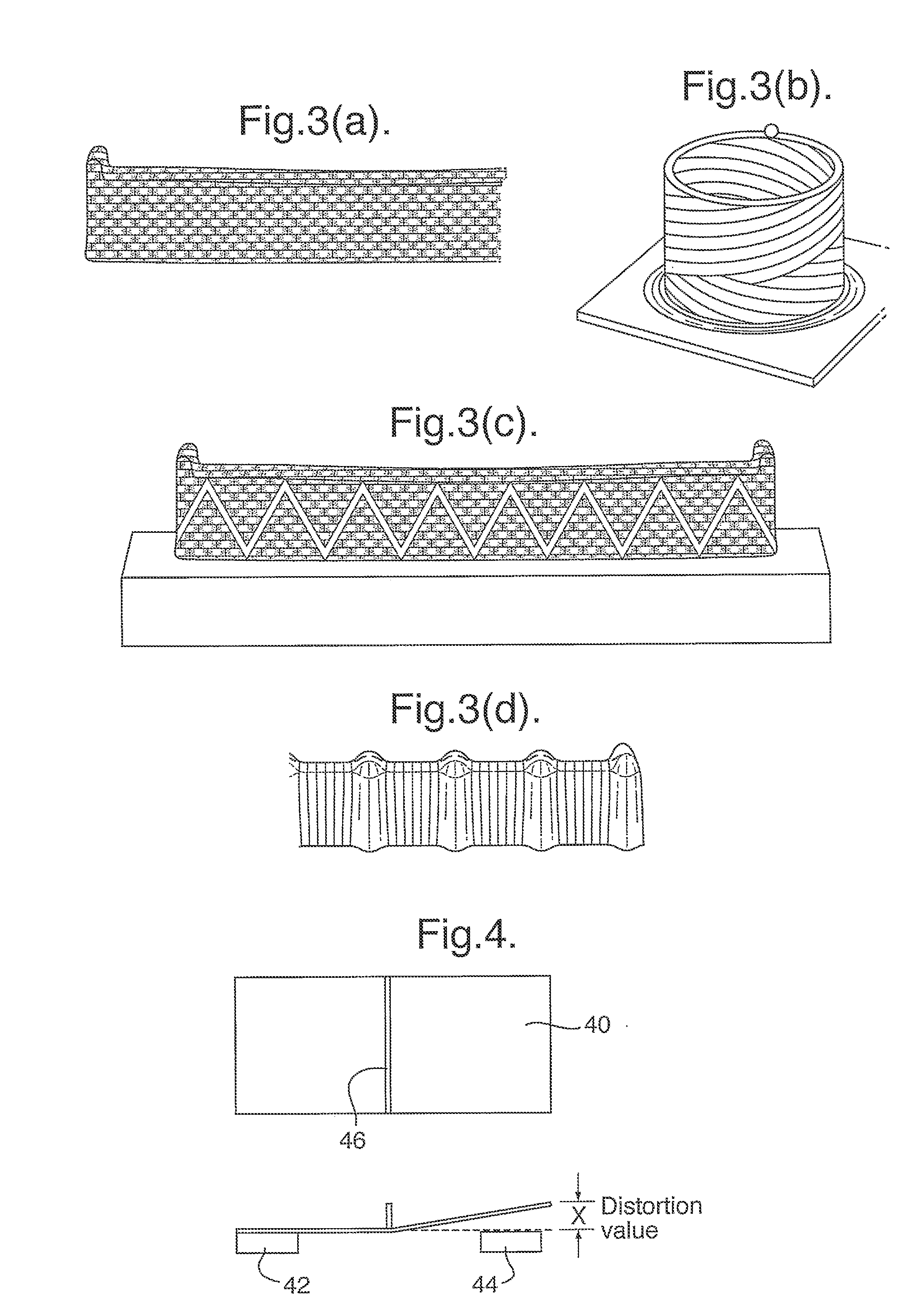
[0022]FIG. 3 shows structures fabricated by means of the invention;

[0023]FIGS. 4 and 5 illustrate experiments performed to demonstrate an aspect of the invention, and

[0024]FIG. 6 shows test pieces fabricated in the experiments.

[0025]Referring to FIG. 1, an apparatus for selective laser melting comprises a base plate 10 configured to receive a workpiece comprising a parent plate or substrate 12 on to which successive layers of material 14, 16, 18, 20, 22 are built-up as described hereinafter. A laser generator 24 is controlled by a computer 26 to deliver a laser beam via an optical fibre 28 to conventional focussing optics 30, which focus the laser beam to a spot 34 on the surface of the work piece. A powder del...


PUM

PropertyMeasurementUnit
Diameteraaaaaaaaaa
Thicknessaaaaaaaaaa
Poweraaaaaaaaaa

Abstract

A selective layer melting or other additive layer fabrication method in which powdered material is fused by heating it with a pulsed laser, the pulses being modulated whilst the laser is traversing the substrate so as to control the thickness and/or width of the layer being formed. Initial layers of the fabrication structure may be formed more thickly than subsequent layers, e.g. by means of a CW laser, to reduce distortion. This aspect of the invention may be employed independently of the use of a pulsed laser to form the subsequent layers.

Description

BACKGROUND TO THE INVENTION[0001]This invention relates to an additive layer fabrication (ALF) method, that is to say a method in which successive layers of material are added on top of each other so as to build-up a three-dimensional structure. The invention is particularly but not exclusively applicable to selective laser melting, and may be applied both to the manufacture of new articles, or to the repair of used ones.[0002]In selective laser melting a laser beam is used to melt a controlled amount of powdered (usually metallic) material on a substrate, so as to form a layer of fused material thereon. By moving the laser beam relative to the substrate along a predetermined path, the layer can be defined in two dimensions on the substrate, the width of the layer being determined by the diameter of the laser beam where it strikes the substrate. Repeating the movement of the laser along all or part of its path enables further layers of material to be deposited, thereby fabricating a...

Claims


Application Information

Patent Timeline
IPC IPC(8): B23K26/00
CPCB23K26/1411B23K26/3206B22F2003/1057B23K35/0244B22F3/1055B23K26/345B23K26/32B23K26/342B23K26/144B23K2103/50B33Y30/00B33Y10/00Y02P10/25B22F10/36B22F12/43B22F10/25B22F12/41
Inventor WESCOTT, ANDREW DAVIDMORELAND, BENJAMIN RICHARDSIDHU, JAGJIT
Owner BAE SYSTEMS PLC
Why Eureka
Try Eureka