Supercharge Your Innovation With Domain-Expert AI Agents!

Scintillator-photosensor sandwich and radiation detector and production method therefor, embodying same

a technology of photosensors and radiation detectors, applied in the manufacture of electrode systems, electric discharge tubes/lamps, instruments, etc., can solve the problem of expensive known production methods

Inactive Publication Date: 2012-05-31
SIEMENS AG
View PDF3 Cites 2 Cited by
  • Summary
  • Abstract
  • Description
  • Claims
  • Application Information

AI Technical Summary

Benefits of technology

[0007]An object of the invention is to provide an alternative production method for an x-ray detector or an x-ray detector element in which the combination of scintillator layer and photosensor layer is produced more simply and securely.
[0009]Air bubbles can be avoided by sufficiently high contact pressure, in particular in the second lamination step, even without vacuum. The method and the lamination device necessary for this are therefore much simpler and also allow multiple sensor sandwiches to be glued successively in the same lamination device, while in the aforementioned method in the prior art only a batch production is reasonable. Typical sufficient contact pressures in the first lamination process are 1-15 kg / cm2. Furthermore, in this method it is advantageous if the scintillator substrate is thinner than 0.6 mm, preferably approximately 0.3 mm, and is made from aluminum, and at least one anodized layer (also additional reflection layers) should be present on the luminophore side (thus the side of the scintillator layer). This design enables a uniform deflection, which is necessary during lamination in order to avoid air inclusions over large areas. In particular, this is advantageous when the scintillator layer with adhesive film is laminated onto the photosensor layer.
[0022]Moreover, it is advantageous when a scintillator material on a substrate made of aluminum is used as the scintillator layer. Here the aluminum on the side of the scintillator material can be coated with an anodized layer or additional reflection layers.

Problems solved by technology

This known production method is expensive, in particular due to the fact that is implemented in part under vacuum.

Method used


Image

  • Scintillator-photosensor sandwich and radiation detector and production method therefor, embodying same
  • Scintillator-photosensor sandwich and radiation detector and production method therefor, embodying same
  • Scintillator-photosensor sandwich and radiation detector and production method therefor, embodying same

Examples


Embodiment Construction

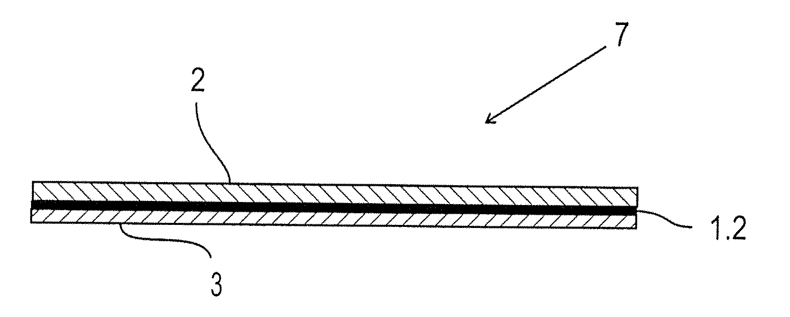
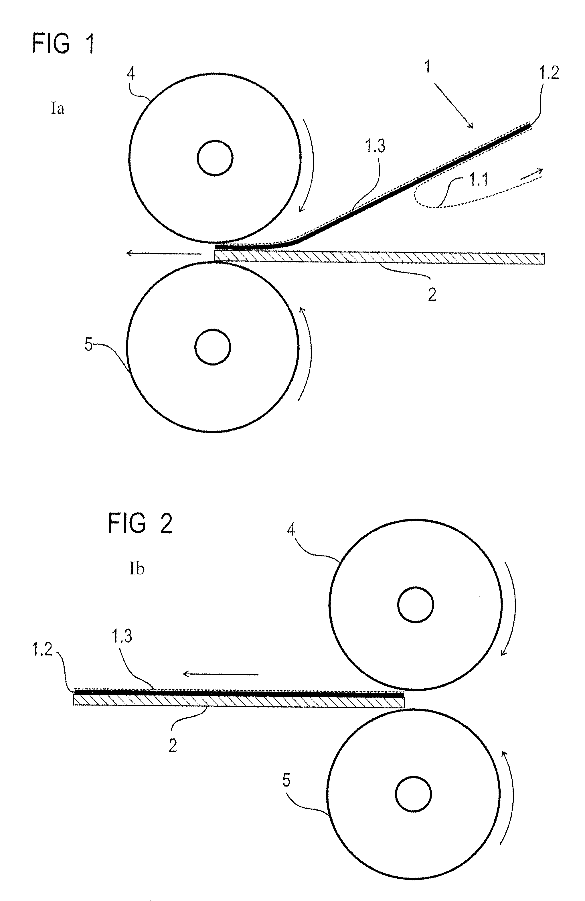
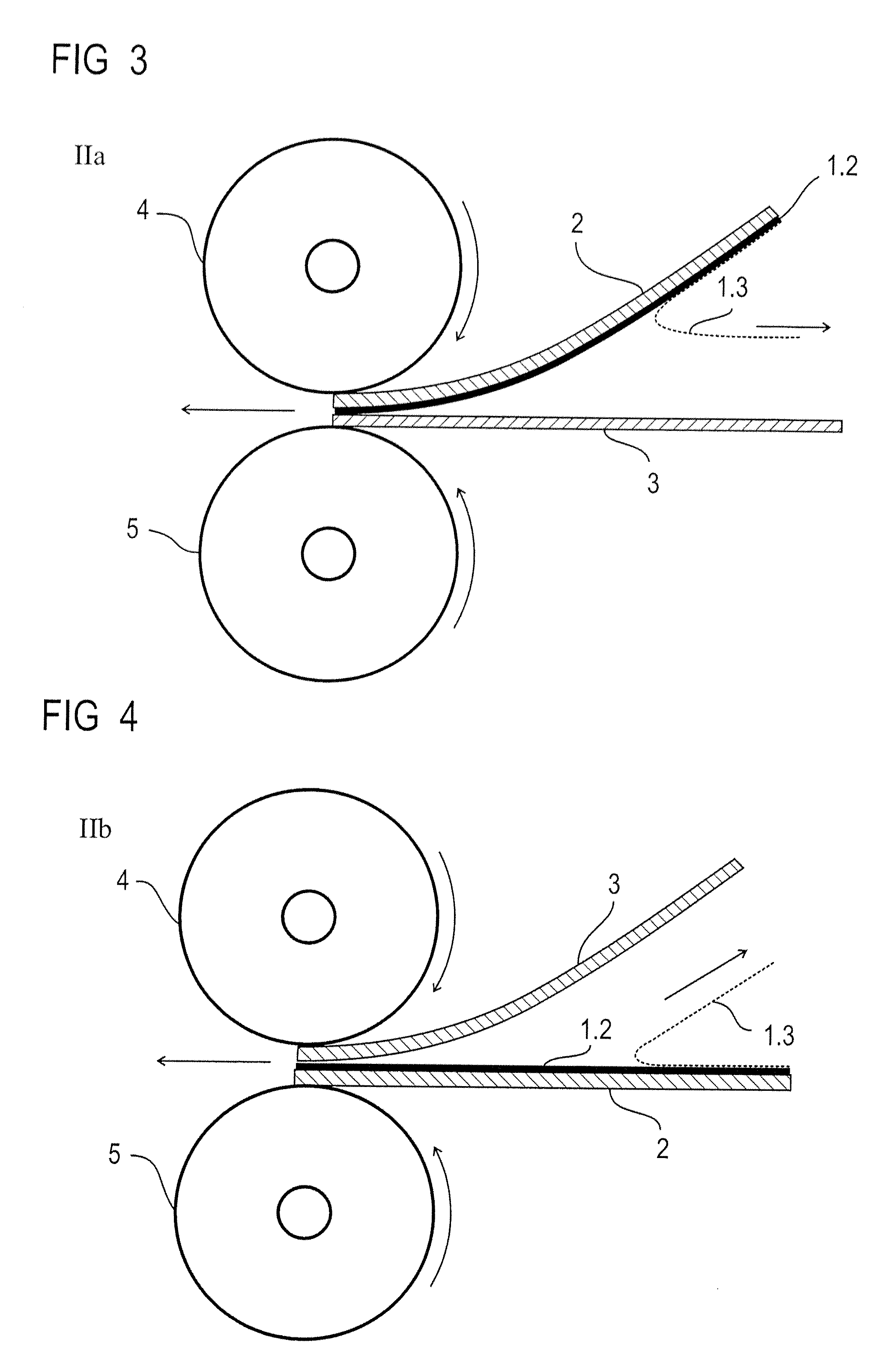
[0030]In the following the invention is described in detail with the use of FIGS. 1-6, wherein only the features necessary to understand the invention are shown. The following reference characters are used: 1: transfer adhesive tape; 1.1: first protective film; 1.2: adhesive layer; 1.3: second protective film; 2: first function layer; 3: second function layer; 4: roller; 5: counter-roller; 6: counter-surface; 7: scintillator-photosensor sandwich.

[0031]FIG. 1 shows the lamination of a transfer adhesive tape 1 comprising an adhesive layer 1.2 and two protective films 1.1 and 1.3 arranged on both sides of said adhesive layer 0.2, wherein a first protective film 1.1 (here the lower protective film) is removed immediately before the application of the adhesive layer 1.2 of the transfer adhesive tape 1, and the remaining transfer adhesive tape 1 (comprising the adhesive layer 1.2 and the protective film 1.3 arranged on top of this) is thereupon placed on a first function layer 2, for exam...


PUM


Abstract

In a method to produce a scintillator-photosensor sandwich for use in a pixel-resolving radiation detector for ionizing radiation, either a scintillator layer or a photosensor layer can respectively be the first and second function layers (alternatively). A transfer adhesive tape carries an adhesive layer having an exposed first side and a second side covered by protective film. The exposed side of the adhesive layer is applied onto a first of the function layers. A first lamination of the adhesive layer including the protective film onto the first function layer is implemented. The protective film is removed. A second of the function layers is then placed in contact with the second side of the adhesive layer that is situated on the first of the function layers. A second lamination of the two function layers with the adhesive layer situated between them is implemented.

Description

BACKGROUND OF THE INVENTION[0001]1. Field of the Invention[0002]The invention concerns a method to produce a scintillator-photosensor sandwich, a scintillator-photosensor sandwich, and a radiation detector with a photosensor sandwich, of the type wherein the scintillator-photosensor sandwich is produced by gluing a scintillator layer with a photosensor layer.[0003]2. Description of the Prior Art[0004]In the manufacture of detectors for graphical presentation of images generated by ionizing radiation for medical applications and for NDT (Non-Destructive Testing), scintillators, for example CsI:TI on Al substrates or GOS (Gadolinium oxysulfide=Gd2O2S) intensifier foils, are arranged over photosensors such as CMOS (Complementary Metal Oxide Semiconductor) arrays or CCD (Charge Coupled Device, i.e., a light-sensitive electronic component arrays), in particular with amorphous silicon (a-Si) technology. The scintillator layer is either only pressed on or is glued. The gluing has the advan...

Claims


Application Information

Patent Timeline
IPC IPC(8): G01T1/20B32B37/12B32B37/14
CPCH01L31/02322
Inventor FUCHS, MANFREDHAUSCHILD, BERNDLOWACK, KLAUSMAURIESCHAT, UWEPREISSLER, ADELBERT
Owner SIEMENS AG
Features
  • R&D
  • Intellectual Property
  • Life Sciences
  • Materials
  • Tech Scout
  • Unparalleled Data Quality
  • Higher Quality Content
  • 60% Fewer Hallucinations
Learn More