
Device and method for securing an electric line with a controllable switching element

a technology of controllable switching element and device, which is applied in the direction of emergency protective circuit arrangement, emergency protective arrangement for limiting excess voltage/current, electric apparatus, etc., can solve the problems of shortening the life of the fuse, wear and ageing of the fuse, etc., and achieves the effect of easy matching to the properties

Active Publication Date: 2012-05-31
LISA DRAXLMAIER GMBH
View PDF3 Cites 20 Cited by
  • Summary
  • Abstract
  • Description
  • Claims
  • Application Information

AI Technical Summary

Benefits of technology

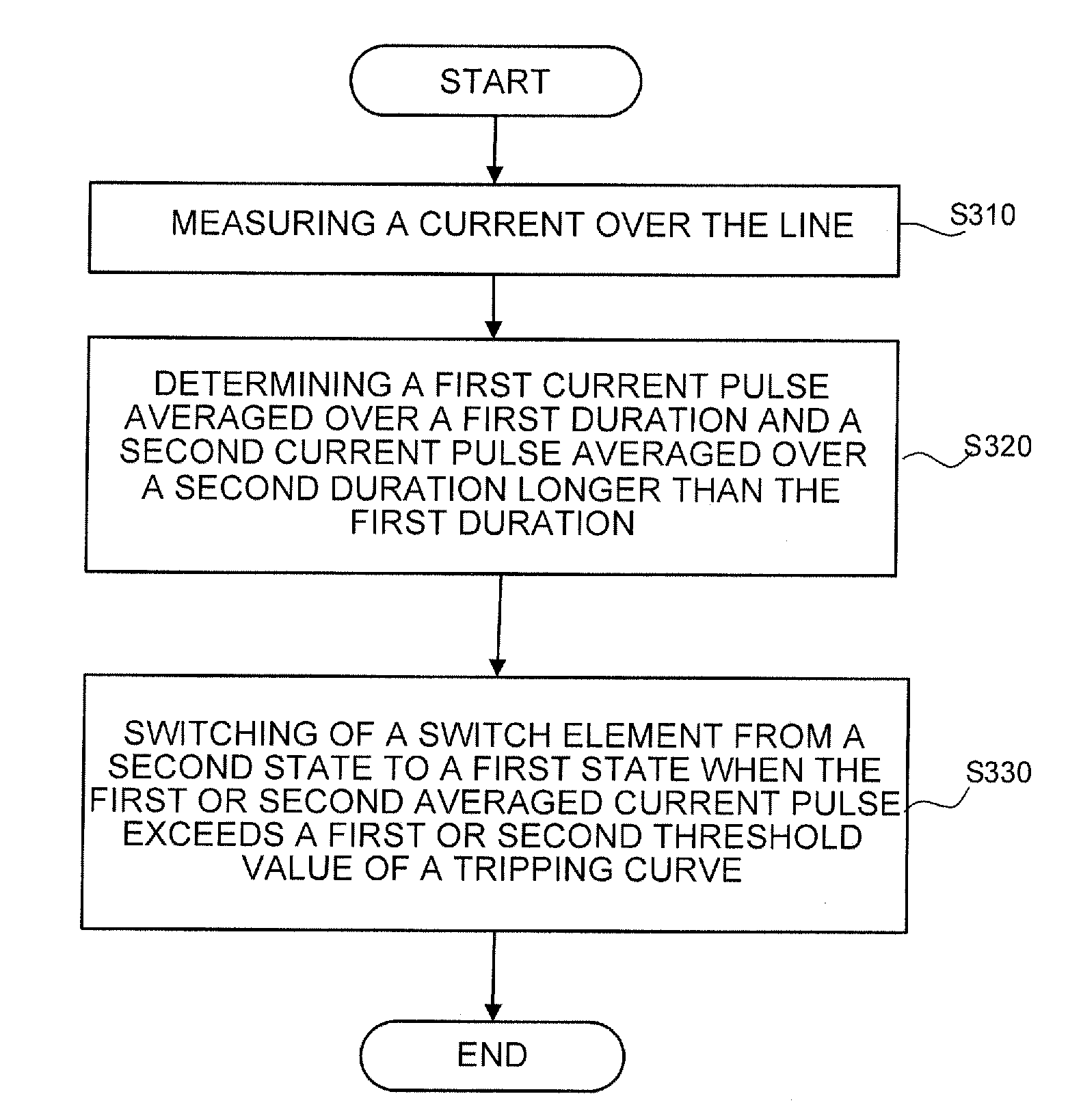
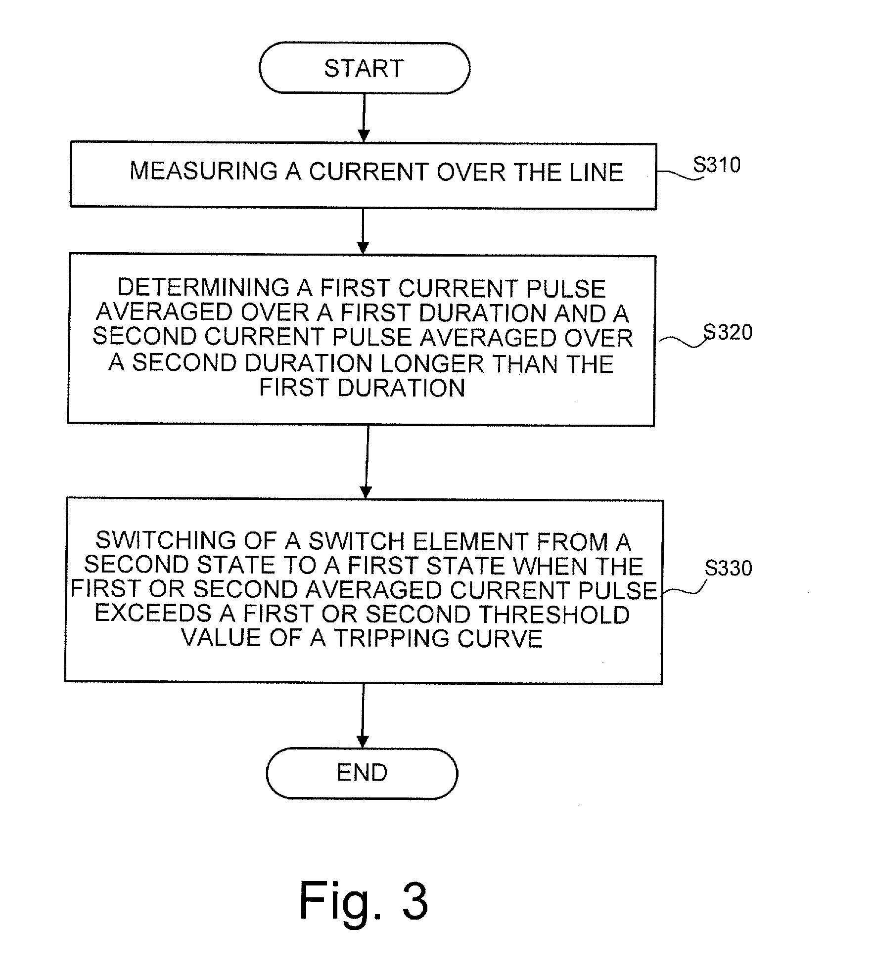
The present invention provides a device and method for securing an electric line that can easily be matched to the properties of the line. The device includes a controllable switching element that can switch to different states based on the current measured over the line. The device can be used in an onboard network for power supply in a vehicle. The method involves measuring the current over the line and determining the first and second current pulses. The device can switch to the first state when the first or second threshold value is exceeded. The invention allows for reliable securing of electric lines and ensures that the load on the fuse is within acceptable limits.

Problems solved by technology

Brief pulse loads characterised by high current peaks can however shorten the life of a fuse, since although under certain circumstances they do not cause problems for the electric line, the fuse can be stressed because the pulse loads come close to the actual tripping conditions so that frequently recurring pulse loads shorten the life of the fuse.
If for example fuses melt in the range from 40 to 50 A, repeated current peaks in the range above 30 A lead to wear and ageing of the fuse.
As the curves for a fuse and line cannot be brought to overlap, a melt fuse cannot optimally protect a line.
In the example shown in FIG. 8 the line is secured in the range of t50 s (uniform load), overload currents (creeping short circuit, overload) can lead to a destruction of the electric line.
As the characteristics of the melt fuse and line are not adapted, in the design of line sets an inherent over-dimensioning of the cross section of the electric line takes place, leading to an inefficient use of resources e.g. copper.
It is therefore difficult if not impossible to find the a fitting melt fuse for a line.
Due to the strong fluctuations in current intensity, it is clear that a thermal model which measures a particular current value in the time range to calculate a temperature only offers sufficient accuracy if the load profile is substantially constant, as a temperature increase in the line depends not only on a current value but above all on how long the current value is present.

Method used


Image

  • Device and method for securing an electric line with a controllable switching element
  • Device and method for securing an electric line with a controllable switching element
  • Device and method for securing an electric line with a controllable switching element

Examples


Embodiment Construction

[0038]Preferred embodiments of the present invention are described in detail below with reference to the accompanying drawings. In the various drawings the same or corresponding elements are designated with the same or similar reference numerals.

[0039]The preferred embodiments of the invention which are described in detail below are described with reference to a device for securing an electric line in a vehicle. It is however noted that the following description contains merely examples and should not be regarded as restrictive of the invention.

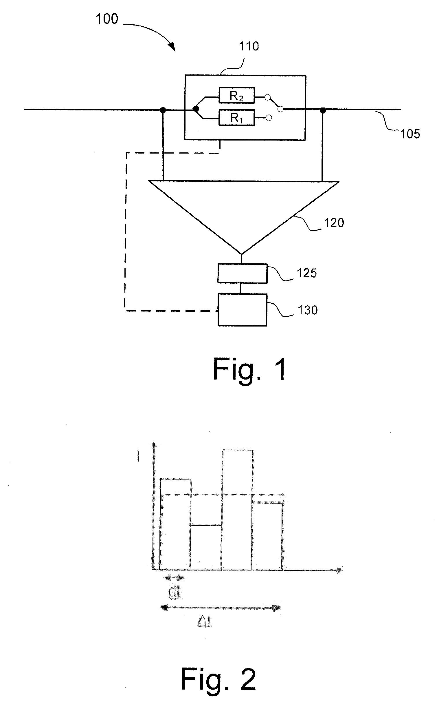
[0040]FIG. 1 shows diagrammatically elements of a device for securing an electric line 105 as can be used for example in a vehicle. The device 100 comprises a controllable switching element 110, a current measuring device 120, an averaging device 125 and a controller 130. The averaging device 125 can also be integrated in the current measuring device 120 or the controller 130.

[0041]As shown in FIG. 1, the controllable switching element 110 is...


PUM


Abstract

The present invention relates to a device and a method for reliably securing an electric line with a controllable switching element, wherein the device and the method can be easily adapted to the properties of an electric line. The device comprises a controllable switching element (110, 610) than is designed to take on at least two states, specifically a first state with a first resistance and a second state with a second resistance that is lower than the first resistance. The invention further comprises a current measuring device (120, 620) for measuring a current via the line; an averaging device (125, 625) for determining at least one first current pulse on the basis of the measured current, averaged over a first duration, and a second current pulse, averaged over a second duration that is longer than the first duration; and a controller (130, 630) for controlling the switching element such that the switching element switches into the first state when the first or the second averaged current pulse exceeds a first or second threshold value of a tripping characteristic curve.

Description

FIELD OF THE INVENTION [0001]The present invention relates to a device and a method for securing an electric line with a controllable switching element, and in particular a device and a method which are formed such that an intelligent control of the switching element secures the line.PRIOR ART [0002]Conventionally, electric lines e.g. in a vehicle are secured by fuses which typically are designed for a uniform load on the line. Previously lines in a vehicle were secured above all by melt fuses. Brief pulse loads characterised by high current peaks can however shorten the life of a fuse, since although under certain circumstances they do not cause problems for the electric line, the fuse can be stressed because the pulse loads come close to the actual tripping conditions so that frequently recurring pulse loads shorten the life of the fuse. If for example fuses melt in the range from 40 to 50 A, repeated current peaks in the range above 30 A lead to wear and ageing of the fuse. Conse...

Claims


Application Information

Patent Timeline
Patent Type & Authority Applications(United States)
IPC IPC(8): H02H9/02
CPCH02H3/087H02H7/228H02H3/0935
Inventor WORTBERG, MICHAEL
Owner LISA DRAXLMAIER GMBH
Learn More