Magnetic Switching Cells and Methods of Making and Operating Same

Inactive Publication Date: 2012-05-31
ZHU JIAN GANG JIMMY +1
View PDF15 Cites 21 Cited by
  • Summary
  • Abstract
  • Description
  • Claims
  • Application Information

AI Technical Summary

Benefits of technology

[0030]Still further objects of the invention relate to processes, techniques, apparat

Problems solved by technology

As technology continues to scale, however, it is apparent that power dissipation and density limits are already slowing further improvements with CMOS, and the c

Method used


Image

  • Magnetic Switching Cells and Methods of Making and Operating Same
  • Magnetic Switching Cells and Methods of Making and Operating Same
  • Magnetic Switching Cells and Methods of Making and Operating Same

Examples


Embodiment Construction

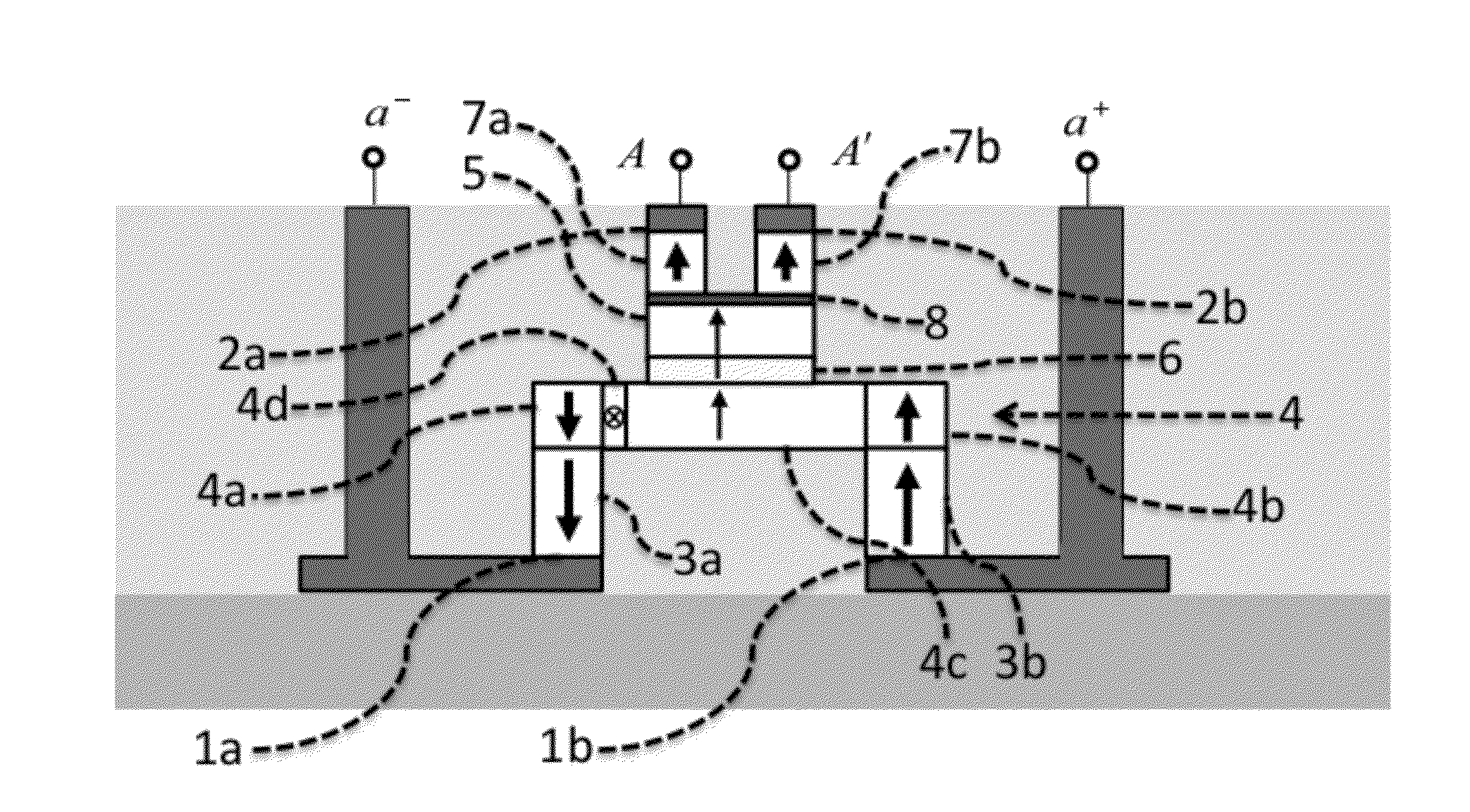
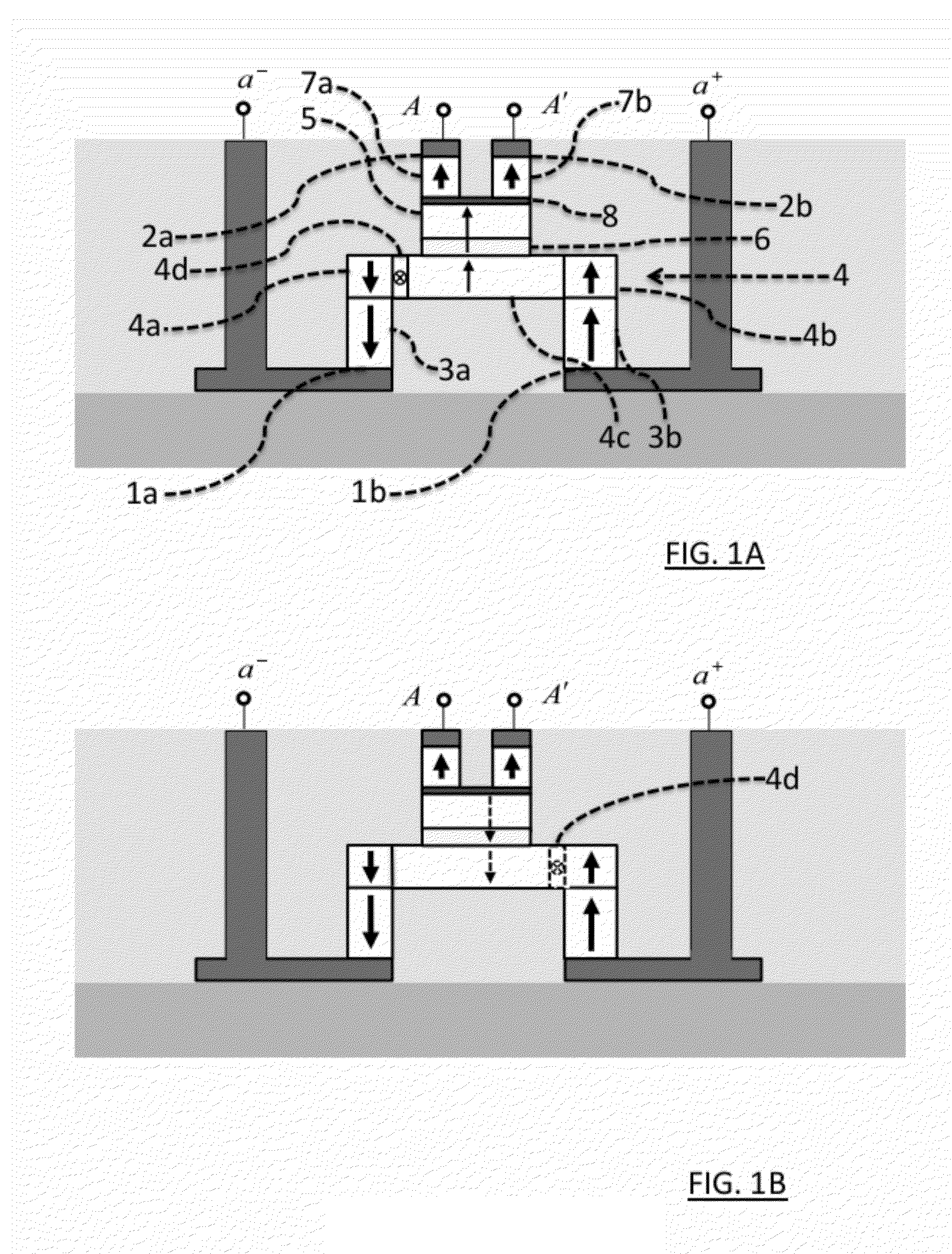
[0063]As previously noted, certain aspects of the instant invention relate to a new magnetic switching cell (mCell) that provides electrical isolation between the current paths used to program—vs. evaluate the state of—the device. Relevant structural and operational features of the inventive mCell are best appreciated with reference to FIGS. 1A-B, which respectively depict an illustrative mCell in its lower-resistance and higher-resistance states. The mCell is a 4-terminal device. As depicted, the mCell includes first and second programming terminals (1a and 1b) that are used to apply currents to switch the mCell between its lower- and higher-resistance states. The mCell also includes first and second evaluation terminals (2a and 2b) that present a first, lower resistance when the mCell is in its lower-resistance state, and a second, higher resistance when the mCell is in its higher-resistance state. [Based on current technology, the terminal-to-terminal resistance in the lower-resi...


PUM


Abstract

Logic circuits based, at least in part, on use of spin-torque transfer (STT) to switch the magnetization—and hence the logic state—of a magnetic material are disclosed. Aspects of the invention include novel STT-based switching devices, new configurations of known STT-based devices into useful logic circuits, common logic circuits and system building blocks based on these new devices and configurations, as well as methods for inexpensively mass-producing such devices and circuits.

Description

CROSS-REFERENCE TO RELATED APPLICATIONS[0001]This application is a continuation-in-part of U.S. patent application Ser. No. 12 / 849,595, entitled “Magnetic Logic Circuits and Systems Incorporating Same,” filed Aug. 3, 2010 by the inventors herein. This application also claims priority from U.S. Provisional Application Ser. No. 61 / 369,743, entitled “Magnetic Logic Circuits, Integration and Fabrication of Same,” filed Aug. 1, 2010 by the inventors herein. These '595 and '743 applications are both incorporated by reference herein.FIELD OF THE INVENTION[0002]The invention relates generally to logic circuits based, at least in part, on use of spin-torque transfer (STT) to switch the magnetization—and hence the logic state—of a magnetic material. Aspects of the invention disclosed herein include novel STT-based switching devices, new configurations of known STT-based devices into useful logic circuits, common logic circuits and system building blocks based on these new devices and configur...

Claims


Application Information

Patent Timeline
IPC IPC(8): G11C11/16
CPCG11C11/16G11C19/0808H01F10/3254H01F10/123H01L43/08H01F10/329H01F10/3286H10N50/10
Inventor PILEGGI, LAWRENCE T.
Owner ZHU JIAN GANG JIMMY
Why Eureka
Try Eureka