
Low-voltage contactor

a contactor and low-voltage technology, applied in the direction of connection contact material, relay, coupling device connection, etc., can solve the problem of difficult automation of the manufacturing process, and achieve the effect of reducing the cost of producing contactors, facilitating handling, and reducing the manufacturing time of contactors

Active Publication Date: 2012-05-31
ABB (SCHWEIZ) AG
View PDF8 Cites 1 Cited by
  • Summary
  • Abstract
  • Description
  • Claims
  • Application Information

AI Technical Summary

Benefits of technology

[0005]The object of the present invention is to provide a stable contact carrier which is easy to be automatically assembled.
[0008]By providing a spring positioner on the framework part and the holder part respectively, the spring is retained in a stable position with respect to the framework part and the movable contact. Meanwhile, the pressed spring between the framework part and the holder part prevents the holder part sliding off from the framework part. Therefore, a stable contact carrier is enabled. In this way the spring is able to produce a desired force on the movable contact so that the contact area is maximized. Therefore, the electrical resistance between the movable and stationary contacts is reduced when they are in contact with each other.
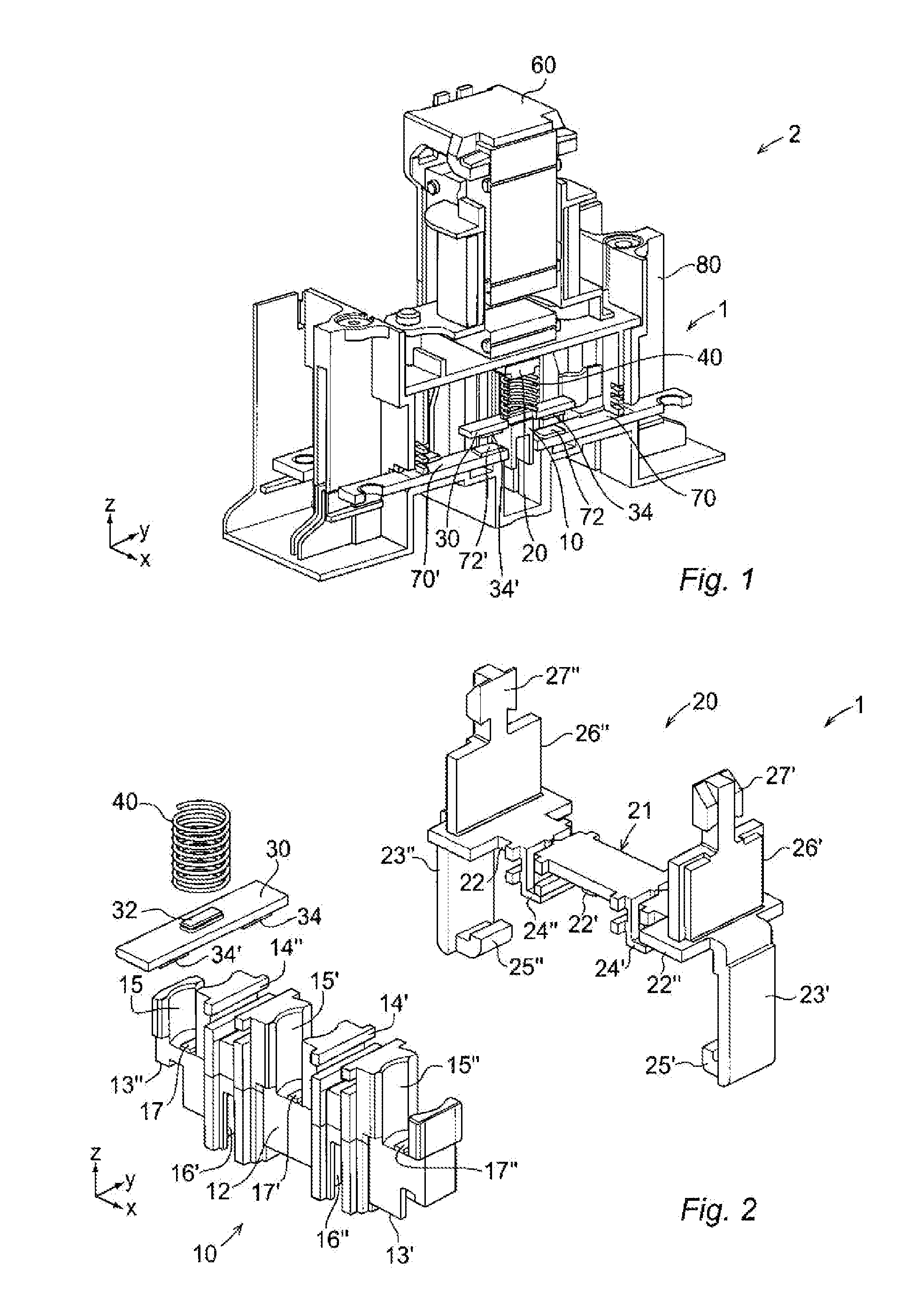
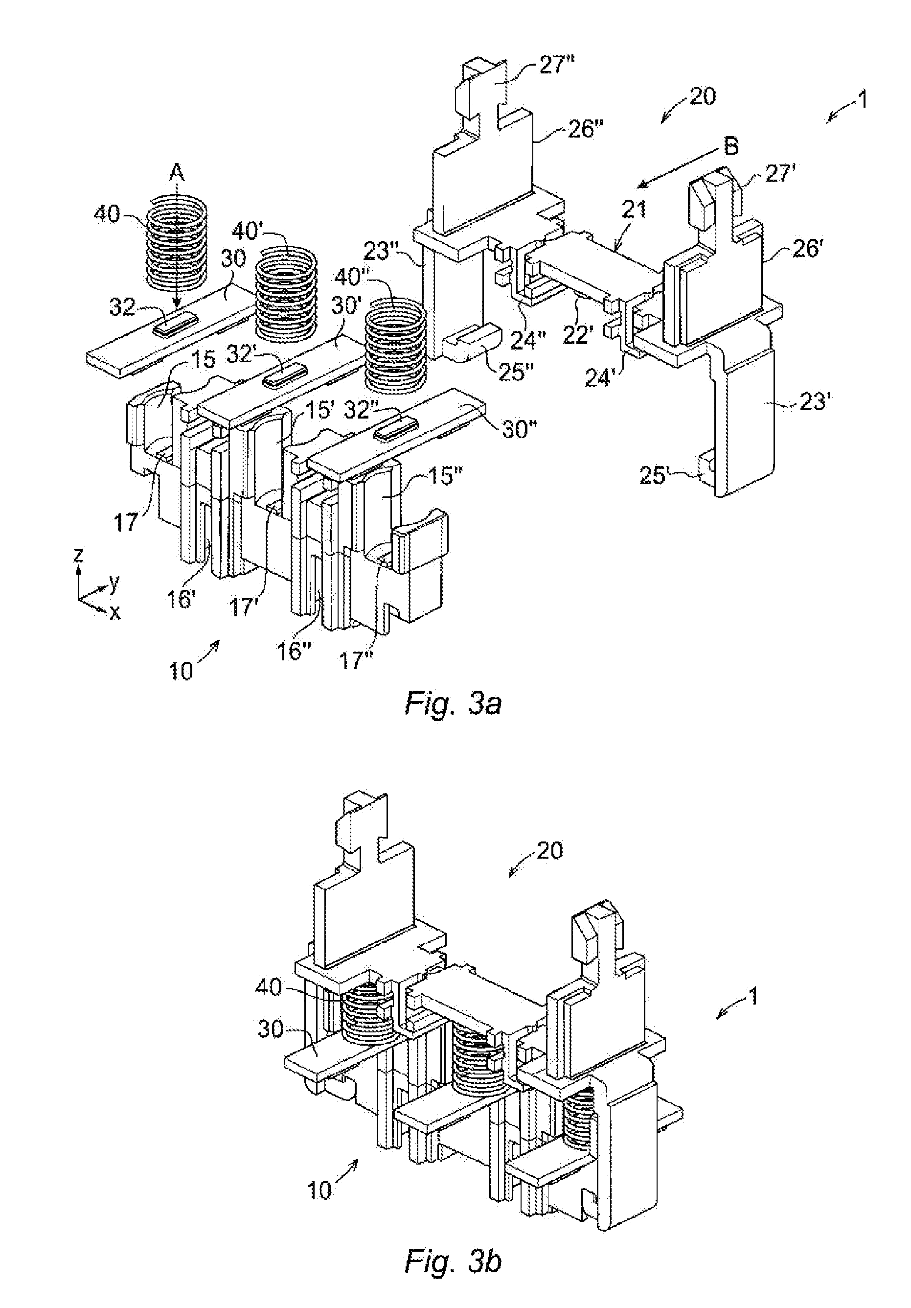
[0009]Due to the fact that the assembling / mounting steps can be performed sequentially in one direction, it is easier to automate assembling process of the contact carrier. An automated assembling may comprise the following steps: placing the movable contact on the holding member of the holder part, placing the spring to the spring positioner of the movable contact so that the first end of the spring is positioned by the spring positioner, pressing the spring down against the movable contact and, as a last step, connecting the framework part and the holder part by the connectors so that the second end of the spring is positioned by the positioner of the framework part, which results in the first end of the spring acting on the movable contact held by the holder part and the second end of the spring acting on the framework part so that the spring is able to produce a force that reduces the electrical resistance between the contacts when they are in contact with each other. All the above steps except the last one may be carried out sequentially in a top-down direction. Therefore, the object of providing a stable contact carrier which can be also automating assembled is achieved.
[0011]Due to the fact that the contact carrier is composed of two separate physical parts, the framework part and the holder part, it is possible to use different thermal and electrical insulation materials with different thermal, mechanical and molding properties to make the framework part and the holder part, respectively. It is advantageous to manufacture the framework part and the holder part using different thermal and electrical materials, since it is then possible to make the framework part of a thermal and electrical material that is easily molded during the manufacturing so the machine processing time of contact carriers is shortened.
[0013]According to an embodiment of the invention, the first thermal and electrical insulation material is thermoplastic material. A thermoplastic is a polymer that turns to a liquid when heated and freezes to a very glassy state when cooled sufficiently. It is advantageous to make the framework part of a thermoplastic material, because such a thermoplastic can go through melting / freezing cycles repeatedly, which makes it more easily handled during the manufacturing compared to thermosetting plastic materials. Therefore, the manufacturing time of contactors is can be shortened considerably and the cost for producing the contactors is therefore reduced. Furthermore, a contactor is often used to control an electric power to another electrical device, for example, a motor. The motor, during its lifetime, will be connected and disconnected to the electric power up to 10 million times. In each such connecting and disconnecting operation, the contact carrier carries the movable contact moving forwards or backwards between an initial position and a final working position to enable a contact or disable a contact with a stationary contact, which means that the contact carrier is constantly exposed to a mechanical deterioration during each connection and disconnection of contacts. By making the framework part using thermoplastic materials which possess the properties of durability and mechanical stiffness, the contact carrier is able to withstand mechanical deterioration. Yet another advantage is that thermoplastic material is re-moldable and recyclable, which therefore is beneficial for the sustainability of contactors.

Problems solved by technology

However, to assemble the movable contact and the spring together with the contact carrier so that the spring acting on the movable contact to produce the force to reduce the resistance between the contacts, a relatively complicated mounting process is used, namely, the movable contact is first placed on the contact carrier from the one side of the contact carrier, then the spring is place, top-down, on the movable contact that is sitting on the contact carrier, the spring has then to be pressed so as, when it is released, to act on both the movable contact and the contact carrier.
Such a manufacturing process is difficult to be automated since the assembly includes steps to be performed from different directions.

Method used


Image

  • Low-voltage contactor
  • Low-voltage contactor
  • Low-voltage contactor

Examples


Embodiment Construction

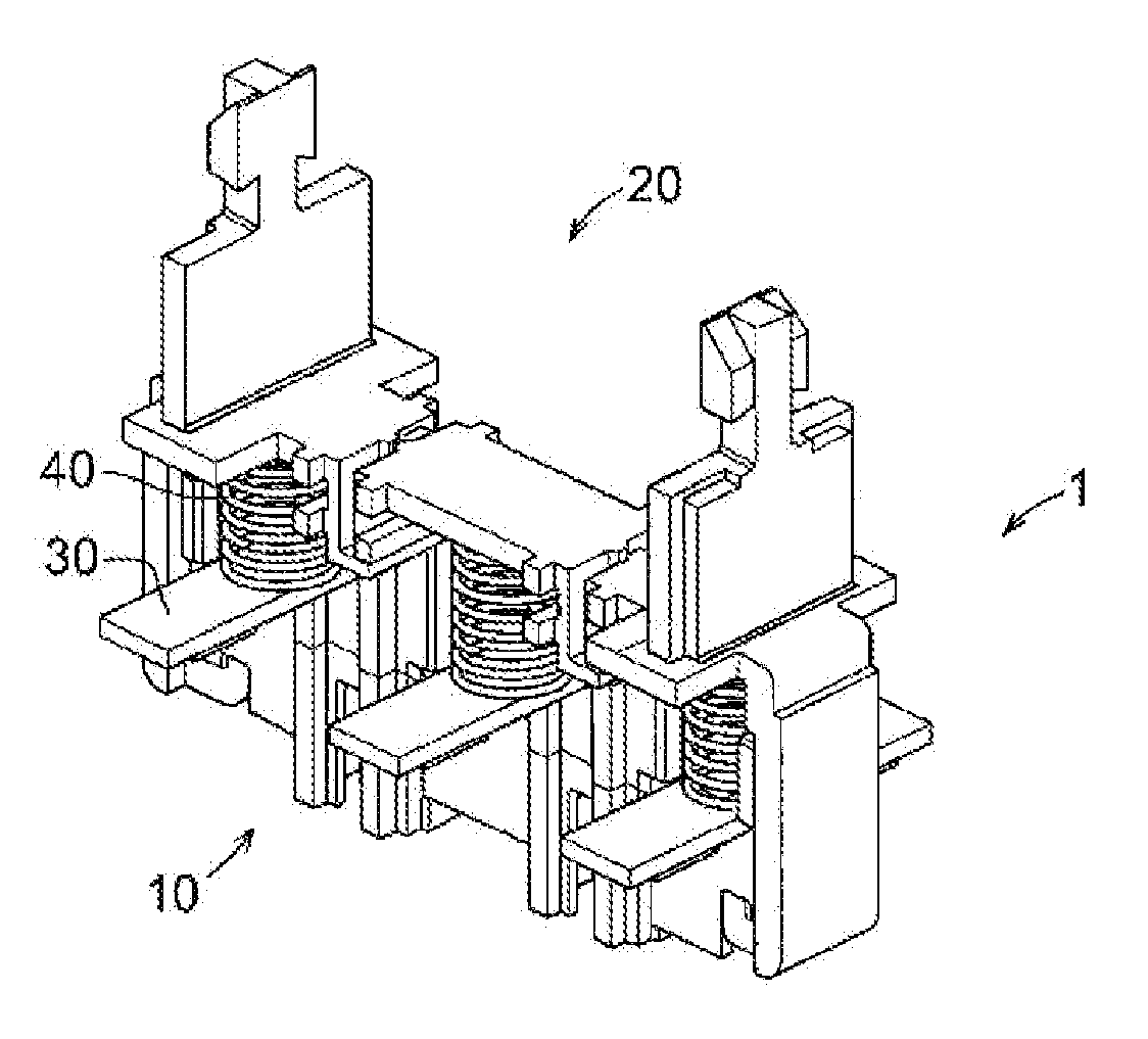
[0019]FIG. 1 shows a partial cross-sectional view of a contactor having a contact carrier, according to a first embodiment of the invention. The contactor 2 includes an actuating unit 60, a stationary contact 70, and a contact carrier 1 having a framework part 20 and a holder part 10 including a movable contact 30 and a spring 40. In this embodiment, the contactor is a three-pole low-voltage contactor. It is understood that the view is a portion of the contactor, and therefore not all the elements of the contactor are illustrated in the figure. The number of the movable contacts depends on the number of the poles. In this embodiment, three movable contacts have been provided.

[0020]The stationary contact 70 is sited on a housing 80 of the contactor 2. In this embodiment, two stationary contacts 70, 70′ are arranged aligned with for each movable contact 30. Each stationary contact 70, 70′ includes a contact surface 72, 72′.

[0021]The movable contact 30 includes two movable contact surf...


PUM


Abstract

A low-voltage contactor with an actuating unit, a stationary contact, and a contact carrier operated by the actuating unit and including a movable contact, a spring with a first end and a second end acting on the movable contact to produce a force that reduces the electrical resistance between the contacts, and a connecting means for connecting the contact carrier to the actuating unit. The contact carrier includes a framework part including the connecting means, a holder part including a holding member adapted to receive and hold the movable contact and the spring. The holder part and the framework part are detachably connected to each other and designed so that the first end of the spring is acting on the movable contact held by the holder part and the second end is acting on the framework part when the framework part and the holder part are connected to each other.

Description

CROSS-REFERENCE TO RELATED APPLICATIONS[0001]The present application is a continuation of pending International patent application PCT / EP2009 / 060076 filed on Aug. 4, 2009 which designates the United States, the content of which is incorporated herein by reference.FIELD OF THE INVENTION[0002]The present invention relates to a low-voltage contactor for controlling an electric power or control circuit of an electrical device such as a motor, a lighting unit, a heating apparatus or a capacitor bank. The range of the low-voltage is up to 1000 V AC or 1500 V DC.BACKGROUND OF THE INVENTION[0003]A low-voltage contactor comprises an actuating unit, a stationary contact, and a contact carrier including a movable contact that is operated by the actuating unit, a spring acting on the movable contact to produce a force that reduces the resistance between the contacts and a connecting member for connecting to the contact carrier to the actuating unit. However, to assemble the movable contact and ...

Claims


Application Information

Patent Timeline
Patent Type & Authority Applications(United States)
IPC IPC(8): H01R4/48
CPCH01H1/2008H01H50/546H01H50/045
Inventor JOHANSSON, MATS
Owner ABB (SCHWEIZ) AG
Learn More