Mobile Radar System

a mobile radar and radar technology, applied in wave based measurement systems, instruments, reradiation, etc., can solve the problems of being a target for enemy attack, becoming a possible enemy target, and forces on the move may not receive the benefits provided, so as to preserve panel array scalability and affordability, reduce quantization lobes, and produce low sidelobes

Active Publication Date: 2012-06-07
RAYTHEON CO
View PDF37 Cites 58 Cited by
  • Summary
  • Abstract
  • Description
  • Claims
  • Application Information

AI Technical Summary

Benefits of technology

[0027]In one embodiment, the system also includes an active monopulse combiner network assembly. This assembly, which is part of an overall monopulse network, enables use of a single panel array design (i.e. a single panel array design part number), eliminates quantization lobes (resulting from correlated weighting at the sub-array level) and produces low sidelobes. This approach preserves panel array scalability and affordability and produces excellent monopulse patterns and an exemplary network is described in co-pending application Ser. No. 12/757,371, filed Apr. 9, 2010 which is assigned to the assignee of the present invention and which is incorporated herein by reference in it's entirety.
[0028]In one embodiment, each panel comprises modular line replaceable units (LRUs). In one exemplary embodiment, a panel which is one (1) square meter (m2) in area is comprised of four (4) weather-tight, electromagnetic interference (EMI) shielded LRU's. Each LRU comprises eight (8) sub-panels, a brazement to cool the sub-panels, four (4) active monopulse combiner network assemblies, four (4) power-logic circuit cards, one (1) distrib

Problems solved by technology

Since such radars are in a fixed position when they are operating (i.e. they can only be operational when they are stationary), they eventually become a target for enemy attack.
First, the fixed radar position, located close to the forward battle line in direct support of brigade operations, becomes a possible enemy target.
Second, forces which are on the move may not receive the benefits pro

Method used


Image

  • Mobile Radar System
  • Mobile Radar System
  • Mobile Radar System

Examples


Embodiment Construction

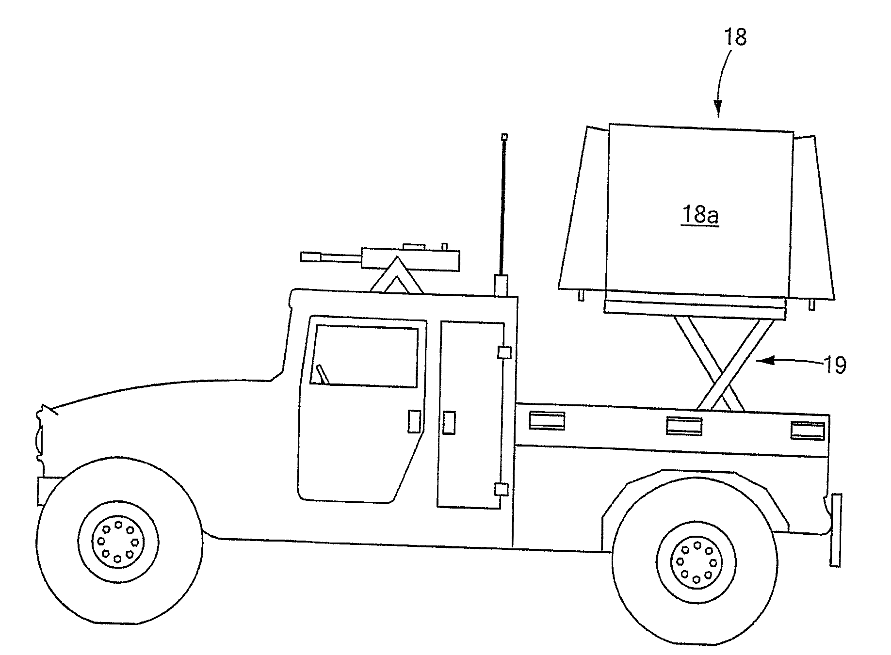
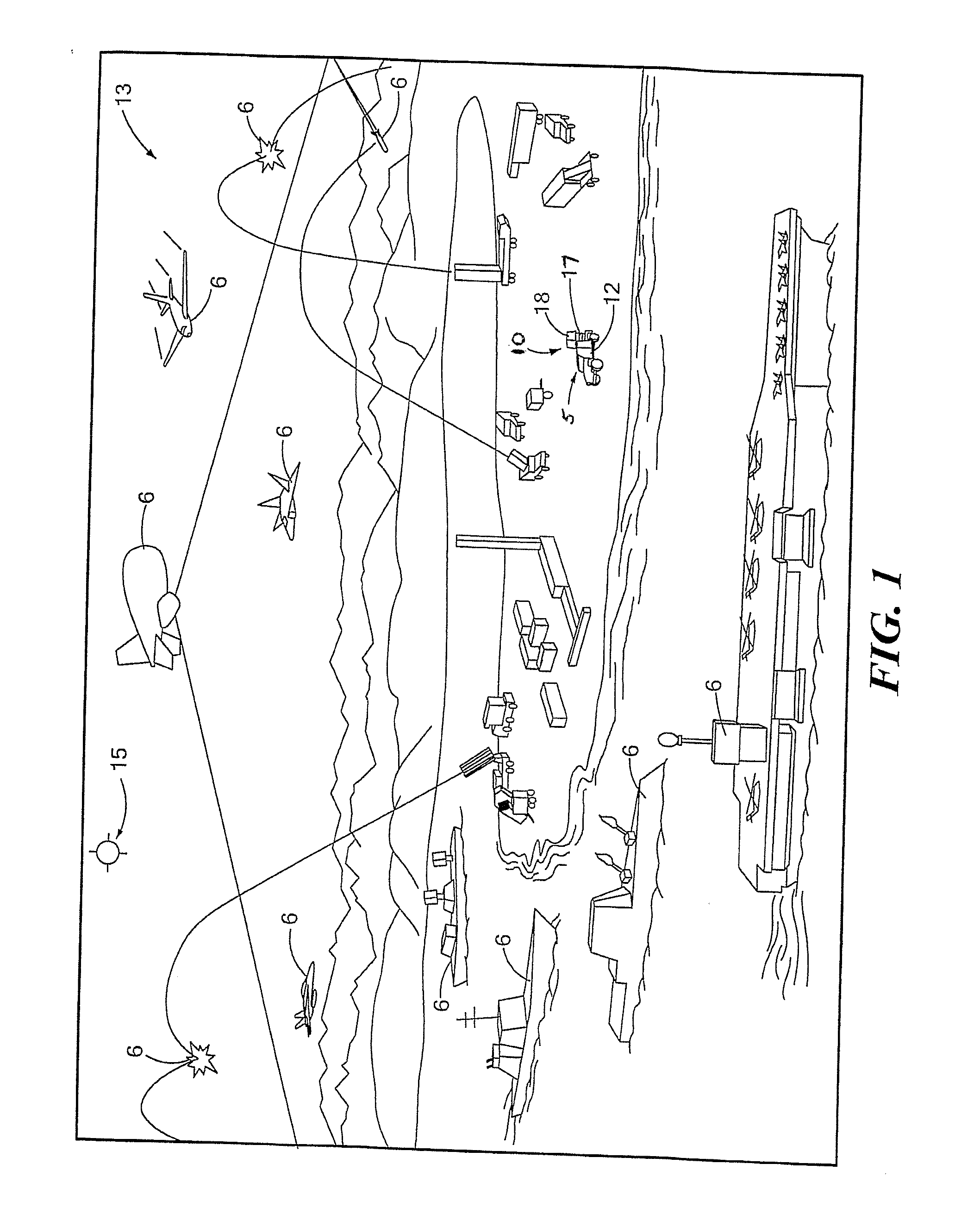
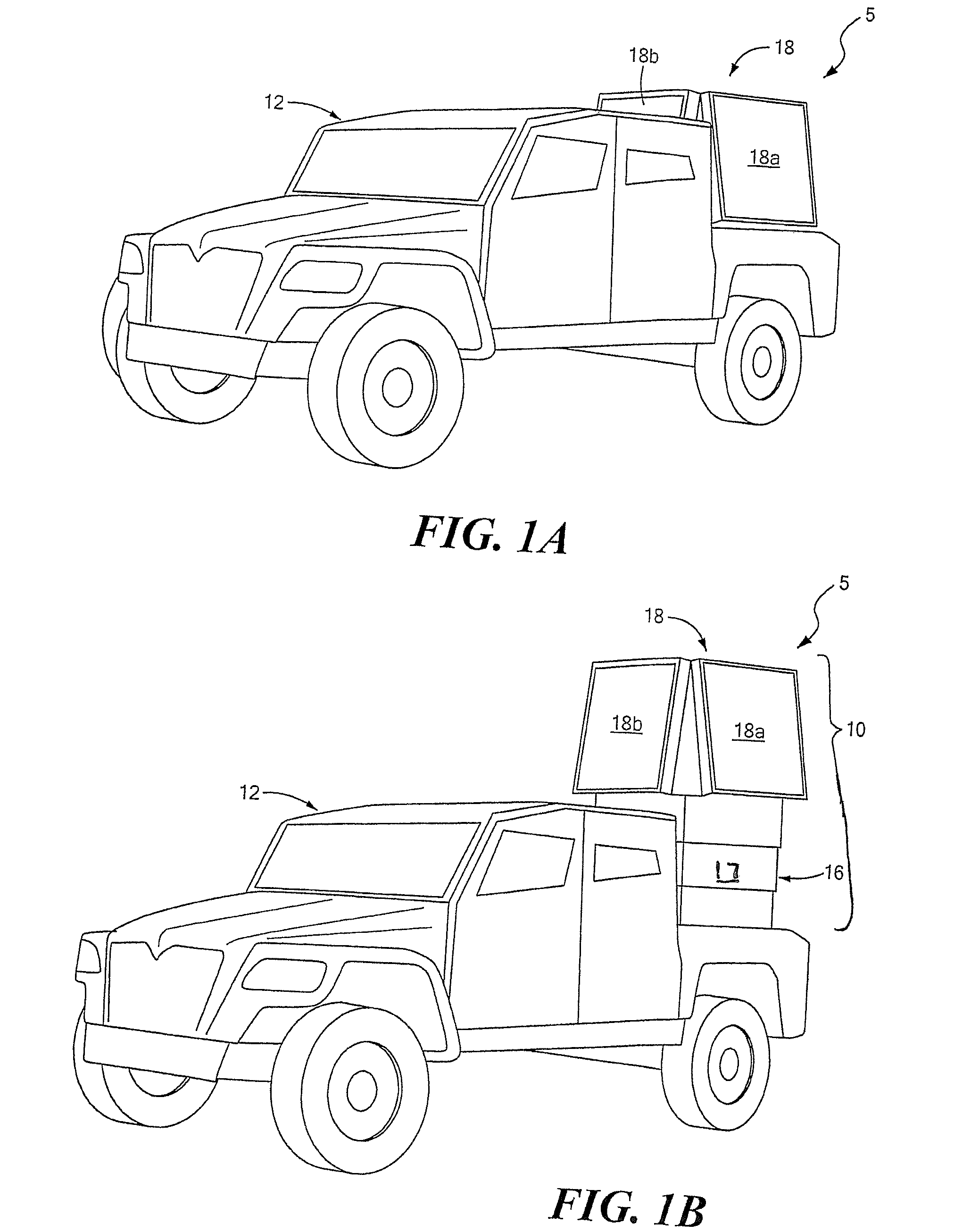
[0044]Referring now to FIGS. 1-1C in which like elements are provided having like reference designations throughout the several views, a mobile radar system 5 comprises a phased array radar system 10 disposed on a vehicle 12. Vehicle 12 travels in and around a battlefield area 13. Vehicle 12 may be provided, for example, as high mobility multi-purpose wheeled vehicle (HMMWV's) or any other vehicle suitable for a transport task. Vehicle 12 and phased array radar system 10 may travel in a variety of environments and terrains, with a clear battlefield environment (i.e. clear of fog, rain, snow, smoke, etc . . . ) and both a relatively flat beach terrain and a mountain range terrain here being show. A global positioning system (GPS) coupled to phased array radar system 10 or vehicle 12 communicates with a GPS satellite 15.

[0045]Mobile radar system 5 tracks aircraft 6 or other objects via phased array radar system 10. Significantly, mobile radar system 5 is operational in either a fixed ...


PUM


Abstract

Described is a mobile radar system which provides both persistent surveillance and tracking of objects with adaptive measurement rates for both maneuvering and non-maneuvering objects. The mobile radar system includes a vehicle having mounted therein an active, electronically-steerable, phased array radar system movable between a stowed position and a deployed position and wherein the phased array radar system is operational in both the deployed and stored positions and also while the vehicle is either stationary or moving. Thus, the mobile radar system described herein provides for longer time on target and longer integration times, increased radar sensitivity and improved Doppler resolution and clutter rejection. This results in a highly mobile radar system appropriate for use in a battlefield environment and which supports single-integrated-air-picture metrics including but not limited to track purity, track completeness, and track continuity and thus improved radar performance in a battlefield.

Description

FIELD OF THE INVENTION[0001]The system and techniques described herein relate generally to radar systems and more particularly to mobile radar systems.BACKGROUND OF THE INVENTION[0002]As is known in the art, there is a great need for highly mobile, medium-range, tactical radar systems that provide information about enemy artillery, mortar and rocket launcher locations for counterattack and other significant threats to warfighters on the ground. Such a radar system must provide high operational availability and reduced maintenance costs.[0003]Conventional radar systems which attempt to serve this function are stowed and typically transported (e.g. towed) by so-called “high mobility multi-purpose wheeled vehicles” or HMMWV's or any other vehicle suitable for the transport task. Such mobile radar platforms are typically located proximate forward battle lines in direct support of brigade operations. Typically, the radar system must be capable of being set up and operational in approxima...

Claims


Application Information

Patent Timeline
IPC IPC(8): H01Q3/00
CPCG01S7/032G01S13/87G01S2013/0245H01Q1/1235G01S2007/406G01S13/86H01Q1/3216H01Q3/46G01S13/723G01S7/406
Inventor PUZELLA, ANGELO M.CUMMINGS, STEVEN T.LICCIARDELLO, JOSEPH A.POZGAY, JEROME H.PEREIRA, STEPHEN J.SARCIONE, MICHAEL G.MORICO, PETER D.ROCHE, JR., JAMES A.
Owner RAYTHEON CO
Why Eureka
Try Eureka